C - E
Cabin depressurisation:
Sudden and rapid depressurisation of the aircraft cabin as a result of structural failure, pressurisation system failure, or deliberate act of the crew.
Air pressure reduces with increase in altitude and therefore the amount of oxygen in any given volume of air also reduces with increase in altitude. Furthermore, the reduction in pressure impedes the ability of oxygen to pass across lung tissues and into the human bloodstream. The condition whereby the concentration of useful oxygen in the bloodstream is reduced because of a decrease in atmospheric pressure is known as Hypoxia.
The degree to which an individual’s performance is affected by lack of oxygen varies depending on the altitude of the aircraft, and on personal factors such as the general health of the person and whether he/she is a smoker. Below 10,000 ft, the reduced levels of oxygen have little effect on most crew and passengers but the higher the aircraft is, the greater the impact of lack of oxygen. Above 20,000 ft, lack of oxygen leads to loss of intellectual ability followed by unconsciousness and eventually respiratory and heart failure. Importantly, the Time of Useful consciousness reduces with altitude - at 35,000 ft the time of useful consciousness is less than one minute. See the separate article on Hypoxia for more detailed information.
The cabins of modern passenger aircraft are pressurised in order to create an environment which is physiologically suitable for humans (Aircraft pressurisation Systems). Maintaining a pressure difference between the outside and the inside of the aircraft places stress on the structure of the aircraft. The higher the aircraft flies, the higher the pressure differential that needs to be maintained and the higher the stress on the aircraft structure. A compromise between structural design and physiological need is achieved on most aircraft by maintaining a maximum cabin altitude of 8,000 ft.
Loss of pressurisation is a serious emergency in an aircraft flying at the normal cruising altitude for most passenger aircraft.
Note that some military flights may involve deliberate depressurisation at high altitude for the purpose of dropping troops or equipment by parachute. Such flights are conducted in accordance with specific procedures and will usually be notified in advance.
Types
- Structural Failure. Failure of a window, door, or pressure bulkhead for example, or in-flight explosion. An in-flight explosion may be due to a system failure, dangerous cargo, or a malicious act such as an explosive device carried on board by a terrorist.
- Pressurisation system failure. Failure of some part of the pressurisation system such as an outflow valve perhaps.
- Deliberate Act A drastic measure but one which an aircraft captain might consider, for example, as a way of clearing the cabin of smoke.
Effects
- Crew Incapacitation. Depending on the altitude of the aircraft when depressurisation takes place, loss of pressurisation can very quickly lead to the incapacitation of the crew and passengers unless they receive supplementary oxygen.
Solutions
- Oxygen. In the event of loss of pressurisation, it is essential that the crew don oxygen equipment as soon as possible. In the case of a deliberate depressurisation, the crew should be on oxygen before the depressurisation commences.
- Emergency descent. In the case of an emergency depressurisation, the crew will want to descend immediately to an altitude at which they and the passengers can breathe without supplementary oxygen - conventionally 10,000 ft.
Centre of Gravity:
In an aeroplane, the centre of gravity (CG) is the point at which the aircraft would balance were it possible to suspend it at that point. As the location of the centre of gravity affects the stability of the aircraft, it must fall within specified limits that are established by the aircraft manufacturer. Both lateral and longitudinal balance are important, but the primary concern is longitudinal balance; that is, the location of the CG along the longitudinal or lengthwise axis.
The empty weight and the empty weight centre of gravity (EWCG) are calculated for each aircraft using a set of weigh scales, the manufacturer defined reference datum, the arms, as listed on the aircraft Type Certificate Data Sheet, for each weighing point. The empty weight of the aircraft is simply the sum of the weights from each of the weighing points. The EWCG is calculated using the calculated moments for each of the weighing points, the calculated empty weight and the appropriate formula for the aircraft type as specified in the AFM (Aircraft Flight Manual). On small airplanes and on helicopters, the center of gravity location is identified as being a specific number of inches from the datum and the center of gravity range is identified the same way. On larger airplanes, the center of gravity and its range are typically identified in relation to the width of the wing. Thus empty weight centre of gravity may be expressed as a percentage of Mean Aerodynamic Chord (MAC) and is often referred to as the "basic index". If equipment is added to or removed from the aircraft after the weighing process, a revised empty weight and EWCG can be calculated mathematically by calculating the moment associated with the change and then modifying the basic index.
For day to day operations, the basic index is used as a starting point for CG calculations. Weight and arm information for the total aircraft load (crew, passengers, freight, fuel, catering etc) are used to calculate moments. The total moment for the load is used to adjust the basic index resulting in the takeoff centre of gravity. Centre of gravity calculations may be done mathematically or graphically at the discretion of the operator.
This section shows data obtained from a NASA Ames research grant for large commercial transport aircraft:
![]()
CG factors for transport aircraft
![]()
CG of components and systems
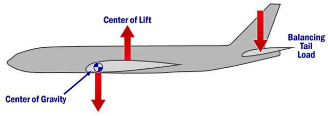
The masses must be distributed so that the center of gravity of the aircraft is located within limits determined relatively to the aerodynamic chord, and the center of lift.
This is required to ensure the stability and the maneuverability, to minimize the efforts on the horizontal and vertical stabilizers and to increase the maximum lift and reduce the drag. On airliners, the center of lift must be located between the CG and the center of lift of the horizontal stabilizer, so that the latter pushes downward to balance the weight.
On airliners the width of the wing is greatest where it meets the fuselage at the wing root and progressively decreases toward the tip. As a consequence, the chord also changes along the span of the wing. The average length of the chord is known as the mean aerodynamic chord (MAC).
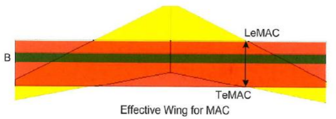
The MAC is a portion of the wing, delimited by LeMAC (leading, 0%) and TeMAC (trailing, 100%). The CG must be located in the MAC.
In large aircraft, center of gravity limitations and the actual center of gravity are often expressed in terms of %MAC (on the roll axis, similar limits exist on the two other axis).

In general, in large transport aircraft, the most forward CG is located as forward as 5% MAC, while the most aft location as aft as 40% MAC. The average CG limits in large transport aircraft are between 20 and 30% MAC.
Using wrong weights for the passengers (adults instead of children) may move the CG to a wrong location, not balanced by the trim, and create strong difficulties during the takeoff and the initial climb.
Check list:
During the flight various checklist is read (for example: Prior to door closure, to Pushback Prior, Prior to takeoff, Prior to landing, and so on). It takes place in a form, when one of the pilot read the text in English and the other after having checked the implementation of the task, the prescribed words to say in English. The check-list s reading is crucial, since these will be ruled out that some tasks - say the landing gear - into the long grass.
In addition to the items listed in the factories and companies are trying checklist drawn up of all error situations or unusual state in which the pilots can meet, such as engine failure, fire in the gearbox, generator failure, an error in the hydraulics, alarm battery range, dehermetizációs indication of the boot and so on. If a fault occurs, the cause list used for the detection and troubleshooting of the help. Of course, their expertise and their practices are also used, but the checklists to ensure that they do not forget an important step off while the situation under control. Error situations covered by the lists (also) during the training, simulation exercises on earth several times over and try to analyze.
The most modern computer systems managed by aircraft checklists for pilots in normal situations sometimes shrank only 2-3 items, the details of the items will examine and configure your computer.
These days the electronic checklists have been around for decades, but were traditionally found in transport category airplanes with high-end avionics. They more recently started showing up in glass cockpits in the new GA aircraft that started rolling off the line in the mid-2000s. Garmin’s popular G1000 glass panel featured an option that allowed pilots to view the checklist on the 2nd screen (MFD) and helped reduce cockpit clutter. Now pilots flying with an iPad can also take advantage of an electronic checklist with affordable apps designed for specific airplane models.
Electronic checklists aren’t for everyone, but there are some real benefits to be gained by using one of these checklists apps over its paper counterpart:
- Less paper–eliminating the need for paper charts is one the reasons you bought an iPad in the first place, right? Using it for your checklist in the airplane allows you to keep your printed version in a side pocket and is one less thing to clutter your cockpit in flight.
- Reliability–how many times have you gone out to a rental airplane to find the checklist torn up, missing pages, or missing altogether? Bringing your own checklist on your iPad ensures you will have the procedures you need on every flight.
- Customizable–most of the checklist apps currently available allow you to start with a checklist designed for a particular airplane model, and then allow you to customize the checklist for your airplane or operation. They make it easy to reorder items or add additional checks as you see fit. One feature to look for is the ability to modify the checklist right from the app, as many of the apps require you to visit a website to make changes, and then manually sync the app for the changes to take place.
- Quick-access to emergency procedures–you’ll find that the emergency/abnormal checklist items are quickly accessible in the iPad apps. Several of them feature a quick-access button to instantly load the emergencies section, and then group them by system, meaning no more digging through pages to find the right section.
- Visual feedback–Most of the checklist apps allow you to check off items on the list by tapping the items as you complete them. While you may find this tedious for things like preflight and starting the engine, many pilots like to take advantage of this during the descent and before landing checks where you may not typically complete the check start to finish in one steady flow. Seeing the checkmarks for what has already been accomplished serves as nice reminder.
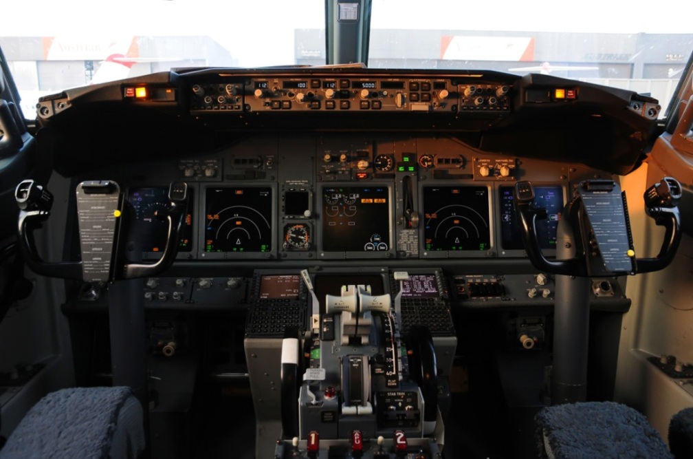
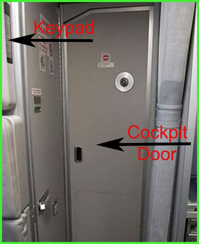
Cockpit door:
Today's passenger aircraft cockpit doors of the structure and system of security has fundamentally changed after the Sept. 11, 2001 events. Unfortunately, after the Germanwings airline of the 9525 flight disaster intensified the doubts about the cabin door, so I try to deal with this issue in more detail than average.
Earlier in the cockpit doors structure of the conventional aircraft made structural materials and their tasks was in the pilot's cabin get on and out (swivel lock through) and one from the inside mechanical lock, in order to prevent unauthorized people from forging into the cabin to get into. Unfortunately, a series of hijacking incidents "warned" the manufacturers to do should something in the interest of safety, until it came Sept. 11 when they have fundamentally changed the situation, and the US aviation authority FAA (Federal Aviation Regulations) provided for all Civilian aircraft in a bullet-proof material and the development of a secure door.
"Telair International" company has begun production of a ballistics-tested and flammability-qualified "hardened" material for aircraft cockpit door and other cabin surface security applications.
The material successfully passed the National Institute of Justice (NIJ) level IIIA threat test and met the FAA -- Federal Aviation Regulations (FAR) flammability requirements in October, 2001. The threat level IIIA ballistic test is specifically prescribed by the NIJ. It calls for the firing of .44-magnum and 9-mm bullets at 1,400 feet. per second into the door panel material, from a distance of 16 feet. Our material met that standard and more.
This critical new material is the result of Telair's heritage as a leader in aircraft systems design and manufacture and over four years' extensive research and development in the area of blast resistant aircraft container systems. While working with the FAA, DuPont and others, the company engineers successfully formulated the lightweight bullet-proof panel material. It is a timely application of Telair's successful blast-resistant technologies program and meets those new criteria for on-board aircraft security now mandated by the federal government.
The panel material is a multi-layer composite utilizing a unique, patent-pending, construction of Kevlar(R), Nomex(R) and Phenolic materials that achieve exceptional weight-to-strength performance, blast resistance and both ballistics and blunt force resilience.
The material weighs less than 2 lbs. per square foot, an important consideration for all airlines, aircraft manufacturers and suppliers who must take overall aircraft weight into consideration when considering any new technology. This is about half the weight of other available materials and it can be customized for thickness, load carrying capacity, and flexural stiffness to suit various aircraft specifications. It is highly resistant to material fatigue and retains most of its structural integrity, even after repeated ballistic impacts.
Telair's business strategy in bringing the technology to market is to immediately provide customized panel material, ready for assembly, directly to OEMs or first-tier aircraft door/cabin/interior manufacturers...and those companies now engaged in aircraft security retrofits. Telair is the recognized world leader in comprehensive aircraft cargo systems for wide and narrow body planes. This new material is the fortunate outgrowth of Telair's ongoing work in the area of blast-resistant cargo systems, and enables us to immediately offer the material in bulk or manufactured to fit any door or bulkhead design.
This ability to manufacture panels to custom specifications is important. The estimated 20,000 commercial aircraft likely to be affected by the call for enhanced interior security are equipped with varied cabin and cockpit door designs. Under the FAA security mandate, these must be hardened by April 2003. These aircraft, and new equipment now in assembly, offer a significant market for the hardened panel material. Telair itself sells to and services the air cargo container systems needs of most commercial cargo and passenger airlines, allowing the company immediate access to this market.
Having explored the structure of the door panel, familiarize yourself with how it looks and how it works these security doors, and its control by the pilots.
The system consists of the following main units:
- The already known door
- Directly from the passenger compartment positioned next to the door panel (keypad)
- A multi-position switch, pilots kézöpső, bottom panel (toggle switch)
- Control Unit, the pilots overhead panel (CKPT DOOR CONT)
- Sound phenomenon buzzer (buzzer)
- Cockpit door surveillance systems (COCKPIT DOOR SURVEILLANCE SYSTEM)
Door
Airbus A320 cockpit door from the passenger compartment
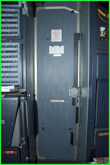
Airbus A320 cockpit door from the cockpit
A forward-opening hinge door separates the cockpit from the passenger compartment. It has three electric locking strikes, controlled by the flight crew. In normal conditions, when the door is closed, they remain locked. When there is a request to enter the cockpit, the flight crew can authorize entry by unlocking the door, that remains closed until it is pushed open.
When the flight crew does not respond to requests for entry, the door can also be unlocked by the cabin crew, by entering a two to seven-digit code (programmed by the airline) on the keypad, installed on the lateral side of the Forward Attendant Panel (FAP).
The door is bulletproof and fully compliant with rapid decompression requirements.A mechanical override enables the flight crew to open the door from the cockpit side. The door has a peephole hole (Spy Hole), through which the cabin environment can be observed before the cabin door.
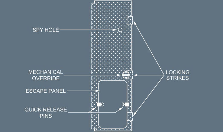
The main units of the door
Note:
1.The escape panel enables the flight crew to evacuate the cockpit, in case of an emergency when the door is jammed. This panel can only be removed from the cockpit side by pulling the quick release pins towards the center of the flap and kicking the panel open.
2.In case of an electrical supply failure, the door is automatically unlocked, but remains closed.
The cockpit door control unit is the system controller, in charge of :
‐Locking or unlocking the door latches, upon flight crew action.
‐Unlocking the door, in case of cockpit decompression (the door then opens towards the cockpitunder differential pressure).
‐Indicating system failures of electrical latches and pressure sensors.
‐Activating the access request buzzer and turning on the keypad LEDs.
The buzzer sounds in the cockpit for 1 to 9 s to indicate that a routine access request has beenmade, or sounds continuously if an emergency access procedure has been initiated.
Keypad
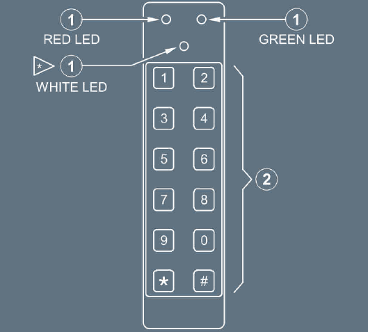
The keypad enables the cabin crew to request access to the cockpit. There are two different accessrequest types : “Routine” and “Emergency” access request.
(1) Locked/Unlocked Door Indicator
GREEN light ON : The door has been unlocked either by a flight crew action, orautomatically (during 5 s) when no flight crew action is performedduring the delay following an emergency access request. Thedoor can be pushed open.
GREEN light flashes :An emergency request to enter the cockpit has been made; thebuzzer will sound continuously in the cockpit, but no action hasyet been taken by the flight crew.
RED light ON: The flight crew has denied access, and the door remains locked.
WHITE light ON :The light comes on each time the cabin crew presses a key on
(2) Digital Keypad
The keypad is used to sound the buzzer in the cockpit for 1 to 9 s (3 s by default), byentering a zero to seven-digit code, as programmed by the airline, followed by the '#' key.It is also used to enter the two to seven-digit emergency code, followed by the '#' key, whenthe flight crew does not respond.
Note:
During the test performed by the cockpit door control unit, the CDLS keypad remains operational, and the CDLS operates as follows: The control unit will store access codes that are entered, and the LOCKED/UNLOCKED DOOR INDICATOR (RED/GREEN LEDs) of the keypad will remain on, as long as the test is running.
‐If the correct access code is entered on the keypad, the buzzer will not sound,until the test is completed.
‐If the emergency access code is entered, the door will unlock. The cockpit buzzer and the LOCKED/UNLOCKED DOOR INDICATOR will be inoperative.
Toggle switch
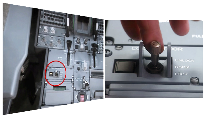
The toggle switch enables the flight crew to lock or unlock the cockpit door, following an accessrequest, thereby allowing or denying the entry to the cockpit.
The multi-position control switch (toggle switch) on the control panel of the lower central pilots. 3 positions, "UNLOCK" position when placing the staff there and holding down the cockpit door is opened. In the "NORM" position to close the door they are fixed in position, and then only in an emergency procedure alakalmazható the part of the cabin crew. "LOCK" position of the door locks, only emergency procedures, beep (buzzer), and the control panel operation at this time is limited to 5 to 20 minutes. After this time, the alarm process may be used for admission. Just quietly I note that the Germanvings 9525 flight, believing that this would have required time period, and then the door could have been opened. The switch is next to a small board, two on the other. If "OPEN" sign is lit, the door is open or not locks. If this tableau is flashing, if the passenger cabin crew started the emergency access program. If there is no response from the pilot's cabin then the door closes only 15 to 120 seconds will be solved too. If the "FAULT" sign lights up the system indicates an error.
OVERHEAD CONTROL PANEL
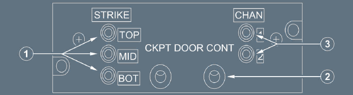
(1)Strikes' status lights
Off:The corresponding (upper, mid, or lower) locking latch is operative.
On:The corresponding (upper, mid, or lower) locking latch is faulty.
(2)Pressure sensor
Two redundant differential pressure sensors enable rapid pressure variation in the cockpit to be detected, in order to command simultaneous opening of all latches when a defined pressure drop is detected.
(3)Pressure sensor status lights
Off:The corresponding (1 or 2) pressure sensor is operative.
On:The corresponding (1 or 2) pressure sensor is faulty.
Note:These indicators enable the crew to identify the faulty item, when the Central Pedestal Fault indicator light is ON.
COCKPIT DOOR SURVEILLANCE SYSTEM
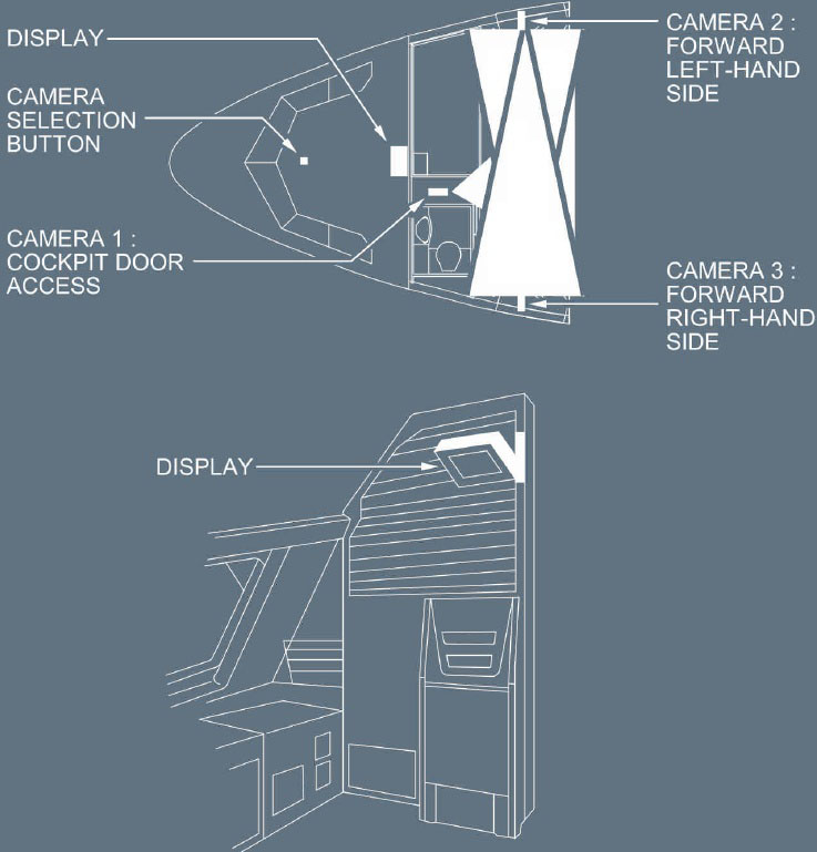
The Cockpit Door Surveillance system consists of three video cameras, which enable the flight crewto identify persons prior to authorizing their entry into the cockpit. An LCD display, located on the rearpanel, shows the various camera views. It has automatic brightness adjustment and is activated bythe Cockpit Door Video pb.
Finally, we look at all of the above into practice:
Cockpit windows:
Wonderful experience through the cockpit window to enjoy the spectacle of sunrise, usually of intercontinental flights, from west to east, such as drivers feel over flights to Europe. However, the cockpit windows, a sight too, is a very critical part of the aircraft. Just think, the aircraft moving at high speed, it is exposed to external influences (bird strikes, icy storm zone, etc.), as well as the pressurized fuselage strength effects, but let's just sequentially.
The cockpit glazing must be adequately view and the view angle values for each type of regulated standards, such as pre-Gazing down: 15 °, up 30 ° and ± 90 ° sideways.
The development of appropriate glazing very serious task of passenger airplanes, as with the large glazed surface of the window frame bears the burden arising from the internal pressure and external aerodynamic forces. So the pressure-bodied aircraft in the window and the frame is load-bearing. The window frame should be not only a large static and fatigue strength, but also very stiff, because the elastic deformation of the glazing frame cracking or even damage to you. A variety of models that meet the requirement in different ways, such as steel and aluminum alloy extruded, welded or riveted to the window frame design.
The cockpit glazing must not be damaged even if the max. Weighing 19.6 N (2 kp) flying body (eg, bird) in the glazing boils in flight. The cockpit glazing of organic and inorganic glass is used. The aerospace organic glass (acrylic resin, popularly known as, Plexiglas) properties: good transparency, light resistance, antifreeze, gasoline and oil resistant, fireproof well. The silicate (non-organic) heat-resistant glass, plexiglas what, but fragile. The combination of the two is used, un. Three glass - glass in combination as a two-layer silicate is very soft, a layer of organic glass and glass in them. The layers are bonded in an autoclave under pressure. Removing ice deposited on windows window heating layer is applied (in addition, de-icing fluid) to 10-15 ° C should be ensured. The heat through the glass window, built-in heater wires, electric current occurs. Also known is a solution which has been placed between the layers of wire mesh made of heating the glass, but also to form the surface conductive layer sputtered metal.
Between the window frame and the glass is a flexible material, providing the glass expansion when it warms up, in addition to the rate reduction during cooling and sealing the respective retention.
The cockpit windows, intended to be different and it varies depending on the type of arrangement. As an example, the figure below shows a Boeing 777-300 type aircraft window layout is shown, that in this arrangement, as opposed to the pilots in the flight direction, there are two permanently attached and heated windows and symmetrically on either side we find one opening, sliding or fixed firmly behind him windows.
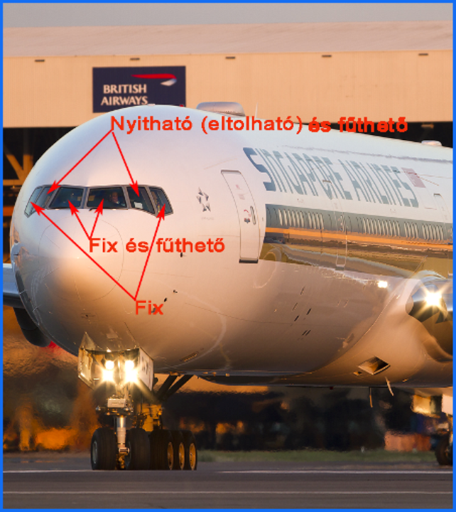
An important, but perhaps the most important task of the open sliding window (in addition to the crews like to "show off" themselves with the window open, on the ground) aircraft emergency situation than it is (ditching, hijacking, suffered a catastrophe aircraft surviving staff of the escape route, etc.). In case of emergency occasion, the crew of the aircraft of the cockpit leave by the overall system of cabin rope, and that the pilots should be exercise regularly mandatory, well, here it is:
Coffin corner:
The coffin corner is the altitude at or near which a fixed-wing aircraft's stall speed is equal to the critical Mach number. At this altitude it can be quite difficult to keep the airplane in stable flight. Since the stall speed is the minimum speed required to maintain level flight, any reduction in speed will cause the airplane to stall and lose altitude. Since the critical Mach number is the maximum speed at which air can travel over the wings without losing lift due to flow separation and shock waves, any increase in speed will cause the airplane to lose lift, or to pitch heavily nose-down, and lose altitude. The "corner" refers to the triangular shape at the top right of a flight envelope chart where the stall speed and critical Mach number lines come together.
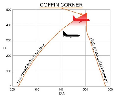
Thus, because of the red figure shows that the range between the stall (stall-speed), and the Mach number is exceeded (overspeed) is reduced to zero at a certain height. Close to forty thousand feet (FL400) has been really tight. In today's airplanes peak height greatly depend on this with a typical. The crossing of the speed of sound normal to disrupt laminar flow, building up pressure wave, the effective wing area so that the buoyancy decreases, besides protection against vibrations job growth, stall, structural damage as well.
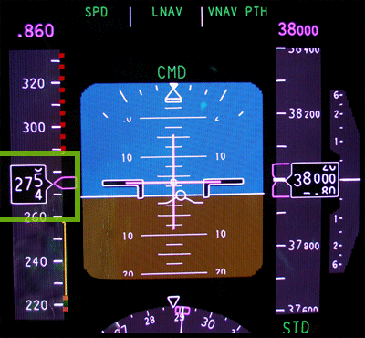
So the loss of high-speed signal trouble running. Thus, because we figure a cruising altitude (38,000 feet) primary aircraft flying display (PFD st). On the left side you can see that all the aircraft's speed must be within the range of about 30 knots. Above it exceeds the allowable Mach number, and below it occurs risk of the stall.
Composite:
Composite materials are becoming more important in the construction of aerospace structures. Aircraft parts made from composite materials, such as fairings, spoilers, and flight controls, were developed during the 1960s for their weight savings over aluminum parts. New generation large aircraft are designed with all composite fuselage and wing structures, and the repair of these advanced composite materials requires an in-depth knowledge of composite structures, materials, and tooling. The primary advantages of composite materials are their high strength, relatively low weight, and corrosion resistance.
The composites or associated are materials such a structural materials, which have two or more different such materials. metal ceramics, ceramics - plastics, ceramics - pottery, metal - plastic, plastic - glass, etc. produced by combining, by means of gluing, and the relationship between them is maintained by increasing the load. The composites are basically divided into two parts: the overall material (matrix) and plug into the second phase (amplifier or associating material). Thus, a fiber-reinforced matrix composites systems. The matrix is the "glue" that holds together the fibers. There are many different types of fibers and matrix systems.
The history of composite materials goes back deep into human history. Five thousand years of north European graves already been reinforced with straw, clay pots. There are many examples demonstrating the resilience and early use of composite materials! The intertwined branches of reinforced earth embankment for flood attack could be better, according to this principle and built earthworks also proved to be more resilient. We all know the adobe, which is a mixture of clay and straw is, it can be made of masonry load-bearing and durability.
In airplanes, the most common matrix of epoxy resin which is a thermosetting plastic. Compared with other materials, such as polyester resin, epoxy stronger and has a much higher temperature. The most common fiber amplifier which is used in aircraft, glass fiber and carbon fiber. Good for fiberglass tensile and compressive strength properties, good impact resistance, easy to work with, and relatively inexpensive and readily available. The main drawback is that relatively heavy. Carbon fiber is generally higher tensile and compressive strength properties, such as glass fibers, and a much higher bending stiffness and is much lighter than glass fibers.
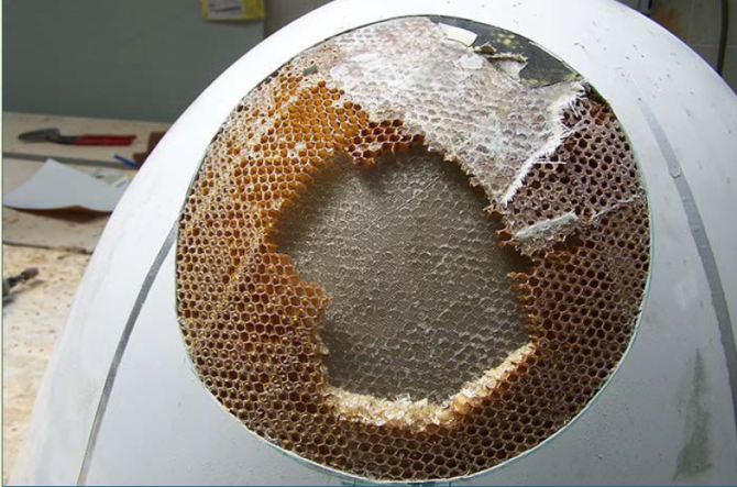
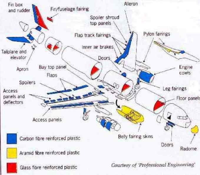
The composites generally bonded together by metal-metal, plastic and plastic. There is actually a sandwich structure, inside which is a so-called hollow honey sleeping (similar to a bee hexagonal Lepe), wearing wrap top and the bottom, which takes over the forces. Thus a high structure is created, which is also called box structure, and a great advantage that is not solid thick aluminum plate is used, which would be ten or twenty times as difficult. The aircraft flap structure (aluminum honeycomb is made), such as preparing the elevator, aileron and the side panels of composite material. The aircraft radome is typically made of composite, specifically "aromatic polyamide" which covered fiberglass inside and out. The nose cone of the most used (impact: bird, ice, and so on) of the aircraft, and in particular seriously damaged in a collision with a bird, which is an example in the figure below, the correction phase:
Repair of the radome
The engine cowlings is made of carbon-glass fiber composite. Where high mechanical stress for example because the wheel pockets stones and other contaminants, there "aramide" (which is similar to the large elm Kevlar, shock-resistant material) coated onto the surface, such as the lower part of the flaps. The advantages of composite aircraft components made of lighter weight, aerodynamic surface can be made smooth, and the fatigue better than metal structures. However, there is a drawback, and this water, which Once in the honeycomb structure, damaging them. The condensate is gradually honeycomb damage, since sustain altitudes of 10-11 km, minus 50 ° C degrees in the water inside freezes, it expands and further damage the honeycomb structure. In the end you start to corrode the aluminum and similar materials cigarette ash remaining. The outer surfaces of composite primer first, then conductive paint, so-called "flame spray" with involvement. It is an aluminum paint, which is blown onto the heated surface, which hardens. The role that aviation resulting from static discharges takes over, which leaves the static discharger. The repairs should be thoroughly cleaned and degreased surfaces, this "methyl II" is used. The surface of the oxide layer must be removed and can be pre-treated chemically (it should be etched in the plate) a phosphoric acid process. The composite structure requires careful pre-and post-production.
Composite Materials In Aircraft
The composite materials are not a new in the aircraft industry; military aircraft widely implemented. Northrop Grumman main structure of the company's B-2 bomber's example, made up almost entirely of composites. This development began in the late 1970s, and the first test flight was conducted with him in 1989. The graphite-reinforced epoxy resin wings made of honeycomb outer surface and internal structure.
The aircraft fuselage also contains a large number of composite aircraft. During the most recent major aircraft development, designed in the mid-1990s models of the Airbus A321 about. 15% (m / m), the Boeing 777 and 10% (m / m) of composite is contained. Today's two newest model is much more composite are incorporated; the A380 weight of 20%, while 50% of the Boeing 787 is advanced from the structural material. The advanced procedures enabled the introduction and economical use of composites in civil aviation. But the adoption and spread of these substances can only go so slowly taking place, particularly exposed to the heavy-indulgence main structural elements. There are three main reasons:
- Failure of the composite material mechanism is still not fully understood,
- Development costs can not be estimated accurately,
- The production costs are high compared to conventional aluminum parts.
The composites raw materials [resin impregnated unidirectional fibers (UD prepreg) resin-impregnated fabric (woven prepreg) and special resins in composites] One of the main supplier of Mitsubishi Rayon Company. These materials are two types of carbon fibers - a moderately flexible and a high-tensile-strength - contain, are produced by the French Structil SA and Japan's Toyohashi Plant.
Composite materials in transport airplane components are being used for decades. Prior to the mid-1980s, airplane manufacturers used composite materials in transport category airplanes in secondary structures (e.g., wing edges) and control surfaces. In 1988, Airbus introduced the A320, the first airplane in production with an all-composite tail section and, in 1995, the Boeing Company introduced the Boeing 777, also with a composite tail section.
Composite materials used in commercial airplanes typically are produced by combining layers of carbon or glass fibers with epoxy.
In recent years, manufacturers have expanded the use of composites to the fuselage and wings because these materials are typically lighter and more resistant to corrosion than are the metallic materials that have traditionally been used in airplanes.
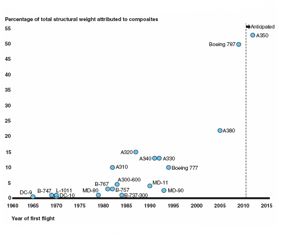
Commercial airplane models over time by percentage of composites
The Boeing 787 is the first mostly composite large transport airplane in commercial service. The Boeing 787 is about 50 percent composite by weight (excluding the engines). It will carry 210-290 passangers on routes of 7650 NM to 8500 NM.
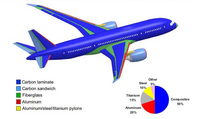
Material used in the Boeing 787
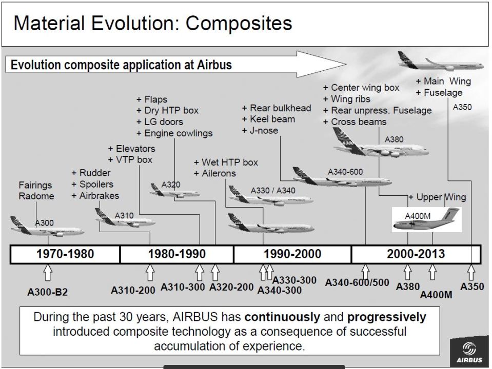
Composite material used in the Airbus
Drag:
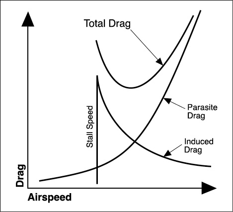
Lift is the first tool you will learn to control and use. The second tool you must understand is drag. There are two types of drag for you to be concerned about:parasite drag and induced drag. Parasite drag is largely beyond the control of the pilot because it comes from such things as struts, fixed landing gear, rivet heads, antennas, and the friction of air passing along the skin of the airplane. Engine cooling drag is 20% of total parasite drag—those air inlets behind the propeller channel a tremendous volume of air over and around the engine. Parasite drag increases as the square of the speed: double the airspeed and the drag quadruples. That is what limits top speed—when all of the available horsepower is being used to overcome drag, you can’t go any faster. The drawings shows how parasite and induced drag vary with airspeed and how each contributes to total drag.
Induced drag is the inevitable result of lift development. Remember how Bernoulli’s and Newton’s effects in combination provide high pressure on the bottom of the wing and low pressure on the top? These forces are resolved at the wing tip as the high pressure air corkscrews up and around the wing tip toward the low pressure area. This meeting of high and low pressure air, with the rotational velocity imparted to the air, creates induced drag.
At large angles of attack with great pressure differences, induced drag is a considerable force; however, as airspeed increases and angle of attack is reduced, induced drag becomes less of a factor. Every time you change the angle of attack, you change the induced drag. Induced drag varies inversely as the square of the airspeed. You will see many modern airplanes with winglets, devices which reduce induced drag by controlling the mixing of high and low pressure air at the tip of a lifting surface.
At high angle of attack, this is a major strength, however, when the airspeed increases or decreases the angle of attack of the induced resistance will decrease. As the aircraft changes angle of attack, in each case varies, the induced resistance. The induced resistance is inversely proportional to the speed of the aircraft. The factories designed Winglets to reduce induced the drag out on the modern passenger aircraft.
Engines Number ( Hajtóművek számozása ):
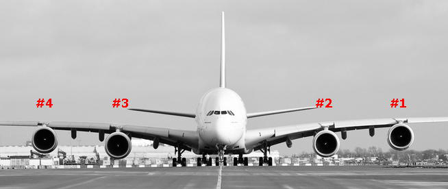
The left of the captain or the port side the engines are numbered from left to right. So if its a twin engined aircraft, engine on left wing is engine number 1 and engine on right wing engine number 2. Similarly for four engined aircraft, the engines on the left wing starting from the tip of the wing is 1 and 2 and right wing starting from the root is 3 and 4.