F - L
FAA and JAA:
FAA is the Federal Aviation Administration. As the Civil Aviation Authority of the USA, it is responsible for establishing aviation regulations in the US. These are known as FARs (Federal Aviation Regulations).
In addition to its regulatory role, the FAA is also responsible for Airspace and Air Traffic Management, maintenance of Air Navigation Facilities infrastructure and has an active role in Research and Development of aviation related systems and technologies.
JAA were the Joint Aviation Authorities, a co-operation of most European (EU and non-EU) civil aviation regulatory authorities. It was not a regulatory body itself, the member authorities were responsible for the regulation.
Originally started as the Joint Airworthiness Authorities in 1970 its objectives were to produce common certification standards for large aircraft and aircraft engines to facilitate a European aviation manufacturing industry (Airbus). Over time, the scope was extended to included aircraft operations, maintenance, licensing and certification/design standards for all classes of aircraft.
With the creation of EASA (see below) in 2002, the EU members transferred the airworthiness regulations away from the JAA. Over time, EASA became responsible for operations and licensing as well. In 2009 the JAA system was disbanded. Only the training organisation (JAA-TO) remains, it mainly provides courses for CAA staff of European countries.
EASA is European Aviation Safety Agency. Created in 2002 by the European Commission, EASA took over the functions of the Joint Aviation Authorities of the EU countries.
The responsibilities of EASA include drafting of aviation safety legislation and providing technical advice to the European Commission and to the EU Member States, airworthiness and type certification of aircraft and aircraft parts for aircraft operating in the EU, approval of aircraft design organisations world-wide and of production and maintenance organisations inside and outside of the EU.
Since its creation, the competences of EASA have gradually expanded. This process is still going on.
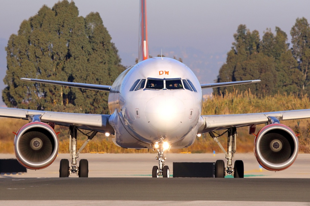
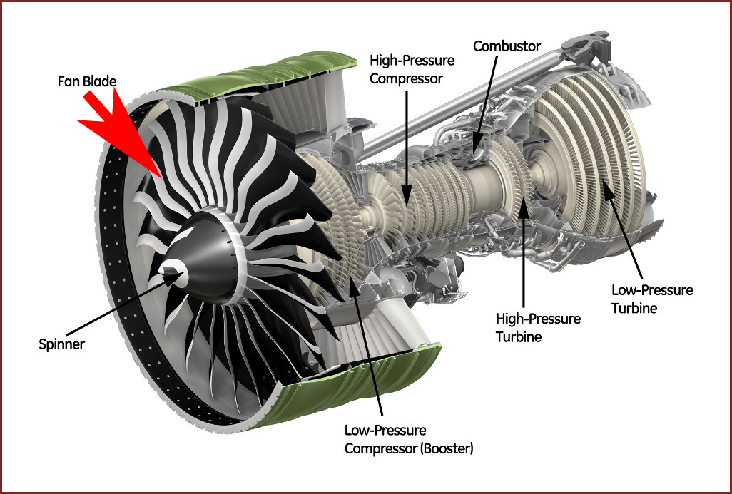
Fan:
The fan section of a turbofan engine is driven by the low pressure (LP) spool. This means that it is connected to two parts of the engine:
- The LP compressor, which must compress the air before it enters the high pressure (HP) compressor
- The LP turbine, which must receive the air after it exits the HP turbine
The problem is that the HP section is efficient at high RPM. But the fan will reach aerodynamic limits as the fan tips pass supersonic speed. Fan blades are also harder to contain in the event of a failure as they spin faster. So to accommodate the fan, the LP section has to spin at a slower speed, which makes it harder to match with the high RPM HP section.
There is also a limitation on air flow. The fan must be able to move a maximum amount of air, which is takeoff power at sea level. But it must also be able to function efficiently at cruise level, where the flow is faster but much less dense.
Engine companies use different strategies to deal with these limitations.
GE (General Electric Engine) mainly makes the LP sections larger in diameter. This allows the blades to have a high velocity at lower RPM. This this requires the air flow to change direction more rapidly.
General Electric Engine

Rolls Royce Engine
Rolls Royce has created a 3 spool design, which allows each section to spin at a more optimal RPM. This adds complexity to the design.
Pratt and Whitney Engine
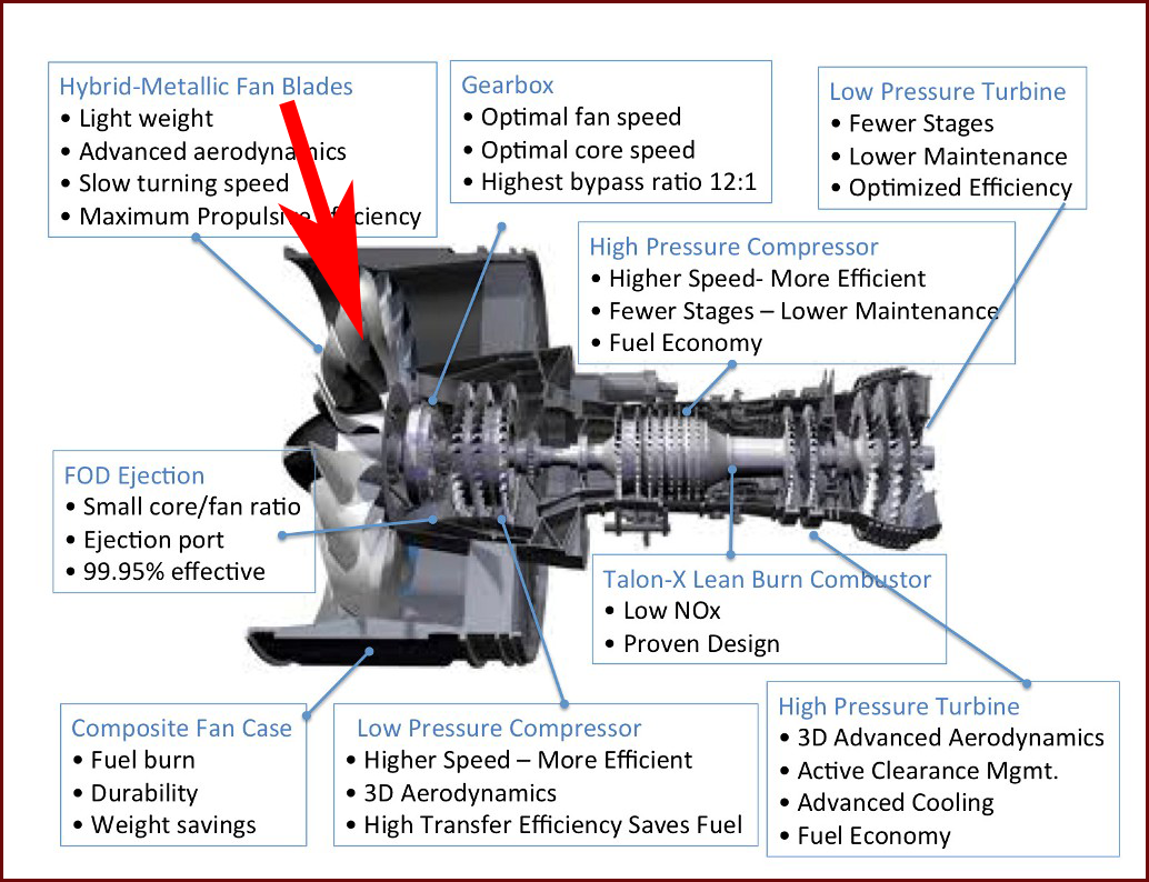
Pratt and Whitney is going with the geared fan approach. Similar to turboprops, there is a gearbox to allow the fan to spin at a lower speed than the engine spool that is driving it.
This allows the turbine spool to operate at a more optimal RPM while still allowing the fan to spin more slowly. A slower fan can be larger, allowing for a higher bypass ratio.
A high bypass ratio allows a turbofan engine to drive more air (produce more thrust) for less air going through the core (burn less fuel). Modern large aircraft have engines like the GE90 on the 777 (9:1 bypass), with the latest engines on the 787 going even higher with the GEnx (9.6:1 bypass), and Trent 1000 (10.8:1). Smaller aircraft like the 737 and A320 currently use engines like the CFM56 (5.5:1), with the new LEAP going higher (9:1 or 11:1). The PW1000G goes even higher (up to 12:1).
Flight Attendants and Pilots Bedrooms:

When you're on a long-haul flight to Asia from across an ocean or continent, you know how important it is to get some sleep.
But what if you're a member of the flight crew? It turns out that Boeing's 777 and 787 airliners have a secret stairway that leads to a tiny set of windowless bedrooms for flight attendants and pilots. After all, they also need sleep on journeys than can take 18 hours or more. Passengers aren't allowed up there, and few people know they even exist.
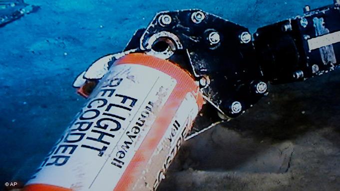
Flight Data Recorders:
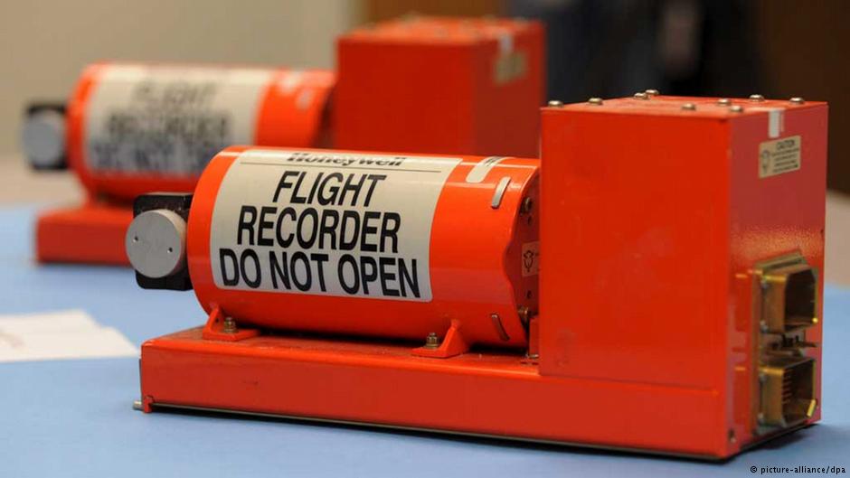
Both boxes are usually located next to each other in the tail section
Essentially, a black box flight recorder is heavily protected recording device, similar to a hard disk or a memory card. The black box records all relevant flight data, in addition to conversations in the cockpit. Previously, this data had to be recorded on two different devices. But today there are also units that can do both. According to regulations, however, every airplane must have two of these devices on board.
Robust, easy to find
A black box must be able to withstand many accident scenarios without sustaining damage. Before being put into use, they are tested to see if they can withstand an impact with a concrete wall at 750 kilometers per hour (about 466 miles/hour), a static load of 2.25 tons for at least five minutes, a maximum temperature 1,100 degrees Celsius (2,012 Fahrenheit) for one hour and water pressure found in depths of up to 6,000 meters (about 19,700 feet).
In order to be easier to find at sea, the devices send out a signal on contact with salt water that can be picked up within a radius of about two kilometers (1.2 miles). At such a short range, the location of the wreck should already be more or less pinpointed in order to find the device.
Everything recorded
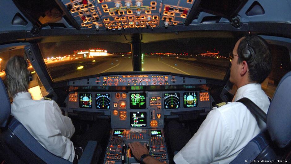
The voice recorder logs all sounds in the cockpit. In addition to discussions between the pilots, it also records automatic computer announcements, radio traffic, discussions with the crew and announcements to the passengers. The sounds of switches and engine are also recorded by the device.
Private conversations between the pilots are also stored on the black box - which is why the captured audio files must be handled carefully, from a data protection point of view. Discussions can only be evaluated in order to clarify accidents or malfunctions. For this reason, the recordings are overwritten after a maximum of 120 minutes; older devices only record 30 minutes. Technically, it's even possible for pilots to stop or delete a recording. In practice, however, BFU's Friedemann said pilots don't make use of that feature.
Ever increasing data quantities
But when it comes to the flight recorder, the second component of the black box, pilots are not able to directly access stored files. In older aircraft, they need to switch on the devices before flight; in modern aircraft, it's automatic.
The amount of data collected has increased significantly in recent years. Today, hundreds, sometimes thousands of parameters are recorded there. This includes information on things like the flight path, altitude, aircraft location, speed, temperature of the engine and exhaust, as well as flap positions, among many others.
Black boxes must withstand pressure up to depths of 6,000 meters
The data helps experts investigate the cause of an accident or serious incident and reduce the potential sources for error. However, investigators do not fully reconstruct a flight. There are only a few specialized agencies worldwide capable of evaluating a black box, and not every agency is able to examine the various models. The BFU can evaluate both Western and Russian devices. But with some models, the experts in Braunschweig must turn to foreign labs for help with the data.
Incidentally, the so-called black box has never actually been black. The color is predetermined: bright orange.
Flight level (FL):
Flight levels are described by a number, which is this nominal altitude (or, pressure altitude) in feet, divided by 100, while being a multiple of 500 ft, therefore always ending on 0 or 5. Therefore, an apparent altitude of, for example, 32,000 feet is referred to as "flight level 320". To avoid collisions between two aircraft due to their being at the same altitude, their "real" altitudes (compared to ground level, for example) are not important; it is the difference in altitudes that determines whether they might collide. This difference can be determined from the air pressure at each craft and does not require knowledge of the local air pressure on the ground.
Flight levels are usually designated in writing as FLxxx, where xxx is a two or three-digit number indicating the pressure altitude in units of 100 feet. In radio communications, FL290 would be pronounced as "flight level two niner zero." The phrase "flight level" makes it clear that this refers to the standardized pressure altitude.
To understand a flight level, we should understand how altitude is measured in an altimeter, which is essentially a calibrated barometer - it measures air pressure, which decreases with increasing altitude. To display correct altitude, a pilot re-calibrates the altimeter from time to time, according to local air pressure.
Flight levels use QNE or pressure altitude, while altitude references QNH or local pressure adjusted to sea level pressure. Altitudes are used at low levels and flight levels at higher levels. The transition between altitudes and flight levels differs by country and is generally just above the highest obstacle in that country. In the US the transition altitude/level is 18,000' / FL180. Some countries transition as low as 5000' / FL050 and the transition altitude/level may vary from airport to airport.
In the altitudes knowing accurate elevations relative to the ground and obstacles is important for collision avoidance and this is the reason QNH is used here. Each airport will report QNH and controllers will issue the current QNH as needed. You need to know the QNH for obstacle / terrain avoidance but you need to be using the same QNH as those around you for aircraft vertical separation.
Above all terrain/obstacles the only thing we care about is vertical separation, so we no longer need to know about the actual pressure and instead use a standard reference pressure, QNE / 1013.25 hPa / 29.92" Hg.
Note that flight levels drop the last two zeros of the corresponding altitude and so 30,000 is FL300, not FL30000. When checking in with a controller, FL300 would be pronounced flight level tree zero zero.
It is also worth noting that an altimeter cannot actually determine altitude. It can only determine pressure (technically local static pressure compared to a reference pressure). It converts this pressure to an altitude using a calibrated non-linear scale. To illustrate the point, look at this map of 500 mb (millibars) heights:
500 mb correlates to 5500 m or 18,000 ft in a standard atmosphere. In a real atmosphere this height varies and is not actually level. An airplane flying "level" at FL180 from LAX to NYC will have actually descended almost 300 m while indicating a constant altitude. These deviations in true altitude from indicated altitude are acceptable, however, since they effect everyone equally in the same locality and separation is maintained.
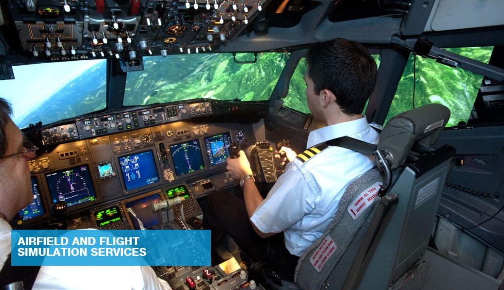
Flight simulator:
Fly-by-wire:
The earliest aircraft were controlled by the pilot simply pulling on a rudimentary cable to move a control surface. However as aircraft became larger, heavier and faster, air loads pressing against ailerons (small moving surfaces on wings), elevators and rudders created forces that could only be overcome by using hydraulic pressure to power them. It wasn’t until the late 1960s that experimental aircraft first used electrical systems rather than mechanical linkage to activate hydraulic jacks which then moved the control surfaces to direct an airplane in flight. Put simply, the pilot’s instructions or inputs from the cockpit were relayed by electric wire to an electric motor that moved the control surface. Major advantages of the electrical systems were lighter weight, less complexity, and easier maintenance, all of which ultimately reduced the airplane’s operating costs.
Fly-by-wire control systems also affected cockpit design, and this is where Boeing and Airbus differ widely regarding the “man-machine interface,” or pilot controls. Airbus took advantage of fly-by-wire systems to eliminate the control columns and control yolks (steering wheels). Airbus pilots use side stick controllers, or ‘joysticks,’ which function kinesthetically like control sticks in a jet fighter. Boeing pilots, on the other hand, fly their airplanes using traditional transport aircraft control yokes mounted on columns. There are advantages and disadvantages to both systems.
A term used to denote the benefits of digital flight control systems in keeping an aircraft from exceeding its design limits during emergency maneuvers is “Flight Envelope Protection.” The flight or performance envelope defines specific limitations for any aircraft that may not be exceeded for safe flight. Parameters involve airspeed, load factor, and altitude. Flight Envelope Protection allows the aircraft to perform necessary maneuvers in an emergency, yet ensures the aircraft’s design limits are not exceeded. Situations demanding such radical performance might be executing a sudden climb or turn at high speed to avoid a mid-air collision, or applying maximum power at low speed when encountering severe wind shear (sudden change in wind direction vertically or horizontally) on landing. Many tragic accidents throughout aviation history resulted from the lack of these safeguards, and today’s impressive safety and reliability statistics are a testimony to the advanced technology represented in fly-by-wire digital flight control systems.
Fonia language:
In the world of aviation, pilots and air traffic controllers use special jargon to communicate with one another. This special jargon, called the Aviation Alphabet, uses the same 26 letters many of us learned in kindergarten. Each letter has a corresponding word used to identify aircraft, often called the tail number, and taxiways, which are just like the roads we drive on.
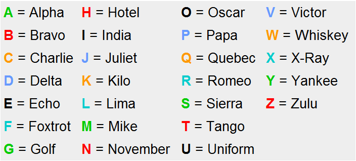
Here is an example of how the Aviation Alphabet would be used between a pilot and the Air Traffic Control Tower:
FunAir Pilot:
"Philly Tower, FunAir 1234 Echo Romeo ready for takeoff."
Air Traffic Control Tower:
"FunAir 1234 Echo Romeo taxi via taxiway Juliet and hold short Runway 27 Right."
FunAir Pilot:
"Roger Philly Tower. Taxiing via Juliet and holding short of Runway 27 Right."
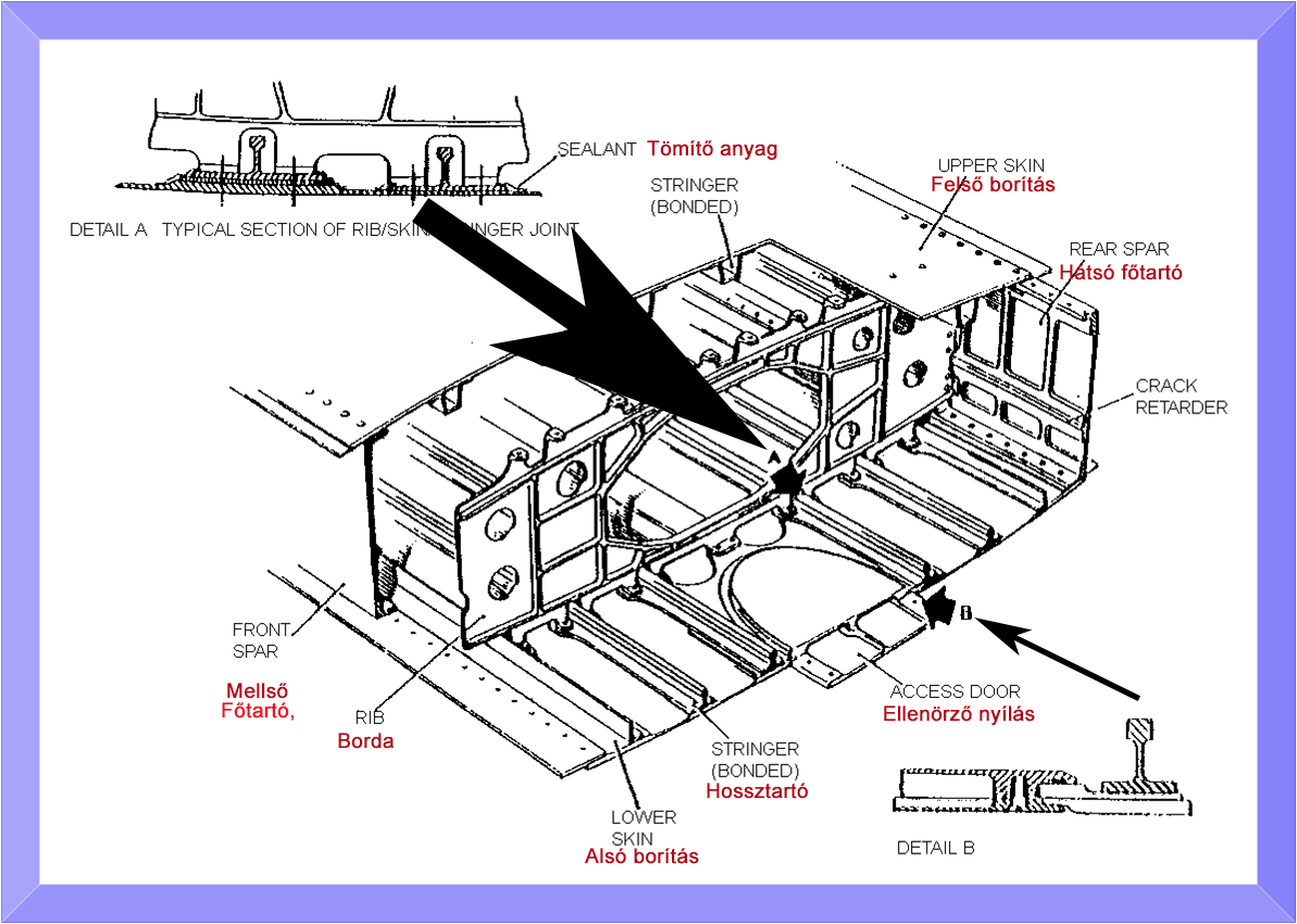
Fuel tanks:
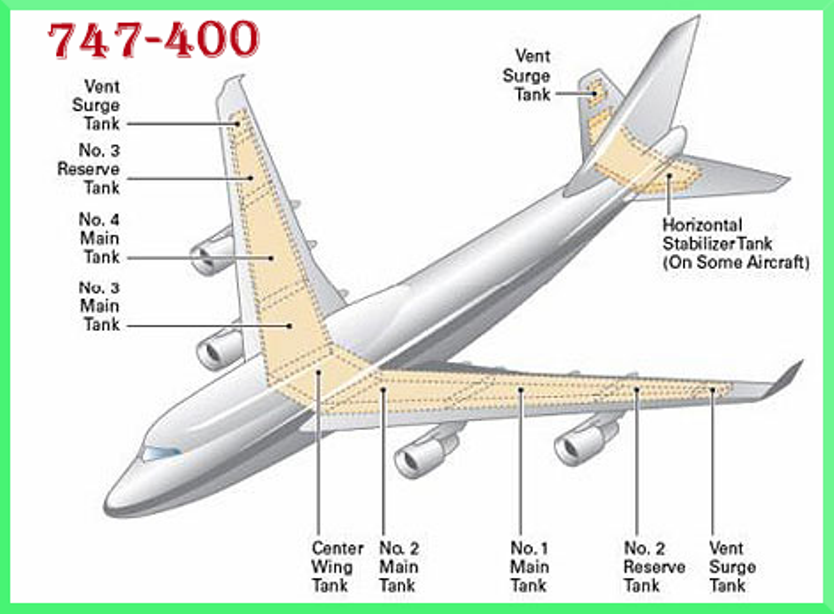
In the general case, civilian aircraft are stored in the necessary fuel (kerosene), in the aircraft wing (Main tanks, tanks Reserve, Vent Surge tanks) and trunk-middle (Center Wing Tank) interior spaces. So the structure of the wing or the fuselage is formed in a container, so-called "caisson tanks". The standard shell structure, the main holders, the cover of the box to form the ribs inside the wings or fuselage. In the case of finished container box is made up of the aircraft fuel tank. In some models the rear of the fuselage and the horizontal control plane (Horizontal Stabilizer tank) fuel is stored, depending on the flight tasks. The wings like riveted shell is not hermetic, insulate must be provided separately. In order to seal the inner surface of the tank associated with a layer of plastic coated with plastic and placed in the overlapped plate surfaces between the rivet seams. The aircraft wing tank is not a single but multi-stage tank. While flying a large role in the "sink" for, in addition to the shell structure because of their role during the movement of the aircraft to ensure the flow (wobbling) attenuation of fuel as well. Along the perimeter of the ribs and torso frames, respectively. rib openings made to ensure the flow of fuel. For verification purposes (routine maintenance, fuel leaks and so on) the maintenance of a person "Inspection opening" - can be absorbed through in to the caisson tanks, of course, after thoroughly ventilate the tanks, and also in compliance with the following strict safety standards. A type 747 "Center Wing tank" size is amazing, just interesting picture, the size, the height of a level mean that a person can stand up in it. The tanks of a complex system (Fuel system: pumps, piping, valves, ventilation systems and so on) transmits fuel to the main engines and auxiliary power units for.
Frequent failures related to the fuel tanks, leaking tanks, tank failure of the inner sealing material (Sealant) due. In all these cases the aircraft when the error is detected should be withdrawn from the flight, and the leaks must be eliminated. Now that airlines make her tremble, because this is a serious outage of the aircraft for them, depending on the severity of the error. It is often difficult to identify the exact location of the leak, where it was believed that there is leaking, there is not the source of the error. The full troubleshooting is very complicated (complete lowering of fuel, remove the Access door , thoroughly ventilate the tank, inspection and service personnel "crawl in" into the tank according to severe security regulations, and finally the tanks control).
When after take-off, in case of an emergency, must return to the base back to the airport due to allowable landing weight limitations imposed on the type of today's modern aircraft in the "open air" into the air are able to let their amount of excess fuel (fuel dump nozzle). For example, the Boeing 747 to 6000 lbs / minute intensity (1 lbs = 0.4535 kg). For this operation (A380-800) staff over the cockpit panel head must take the "FUEL JETTISON" panel labeled "ARM" and "ACTIVE" switches activated. Fortunately, this operation is rarely, but unfortunately sequences based on the following exist:
Huge amounts of kerosene supplied to a long-range passenger aircraft. For example, a 747-400ER model in wells at a long-term flight path and close to US Gallic 67.705 (241.140 L), kerosene spend, which is about to take a New York-Hong Kong route is sufficient (Airbus A380-800 nearly 310,000 liters).

Glass Cockpit:
Modern "glass cockpits" like those in the Boeing 777, the F-117 stealth fighter and Shuttle Atlantis represent a revolution in the way cockpits for aircraft and spacecraft are designed and built today. The first hints of this revolution appeared in the 1970s when flight-worthy cathode ray tube (CRT) screens began to replace a few of the electromechanical displays, gauges and instruments that had served so well for so long. These new "glass" instruments, as few and as primitive as they were, gave the cockpit a distinctly different look and suggested the name, "glass cockpit."
The revolution in cockpit design was born of both opportunity and necessity. Those working to advance commercial airline passenger service felt it first.
Prior to the 1970s, air transport operations were not considered sufficiently demanding to require advanced equipment like electronic flight displays. The increasing complexity of transport aircraft, the advent of digital systems and the growing air traffic congestion around airports began to change that, however.
She added that the average transport aircraft in the mid-1970s had more than 100 cockpit instruments and controls, and the primary flight instruments were already crowded with indicators, crossbars, and symbols. In other words, the growing number of cockpit elements were competing for cockpit space and pilot attention.
What was needed, she explained, were displays that could process the raw aircraft system and flight data into an integrated, easily understood picture of the aircraft situation, position and progress, not only in horizontal and vertical dimensions, but with regard to time and speed, as well.
In response, engineers at NASA Langley Research Center worked with key industry partners to develop and test electronic flight display concepts, culminating in an all-important series of flights to demonstrate a full glass cockpit system. Boeing loaned some of its most promising engineers to the project. Rockwell Collins turned the team's concepts into hardware.
The challenges were many and varied. In designing the experimental system, the research team looked at what information pilots needed to have and how it should be presented to them. One unexpected challenge: Finding the right balance between what the computerized system should manage and what the pilot should manage. The result: A glass cockpit system with an autopilot that increased safety by reducing pilot workload at peak times, yet kept the pilot "in the loop" at all times to maintain situational awareness.
Realistic terminal area flights with the NASA Boeing 737 flying laboratory generated a great deal of interest from airline pilots and other key elements of the aviation industry, and helped state the case for Federal Aviation Administration certification.
The success of the NASA-led glass cockpit work is reflected in the total acceptance of electronic flight displays beginning with the introduction of the Boeing 767 in 1982. Airlines and their passengers, alike, have benefitted. Safety and efficiency of flight have been increased with improved pilot understanding of the airplane's situation relative to its environment. The cost of air travel is less than it would be with the old technology and more flights arrive on time.
The Department of Defense has adopted glass cockpit technology to increase performance of its newest aircraft, from fighter-interceptors to long-range bombers.
Today’s factory-built aircraft come equipped with glass cockpits, which is a fancy name for the advanced technology found on board aircraft. This technology, once reserved for only the most advanced jets, is now available, and even commonplace, for light aircraft. If you haven’t flown an aircraft with a glass cockpit, you will likely find yourself in one very soon.
So what makes a cockpit glass? The term “glass cockpit” generally refers to an LCD display that replaces the conventional “six-pack” of flight instruments in an aircraft. It’s a term given to any aircraft in which the primary instruments are located within a single primary flight display (PFD) or Multi-Function Display (MFD) that looks like a computer screen – a large, flat, glass-panel display. PFDs and MFDs have the capability to display all of the traditional instruments along with lots of additional data such as engine data, checklists, weather and traffic displays.
The typical six-pack on an older aircraft includes six primary instruments (hence the name ‘six-pack’), including the airspeed indicator, attitude indicator, altimeter, vertical speed indicator, turn coordinator and the directional gyro (DG). In a glass cockpit, these instruments no longer exist, and the data is displayed digitally.
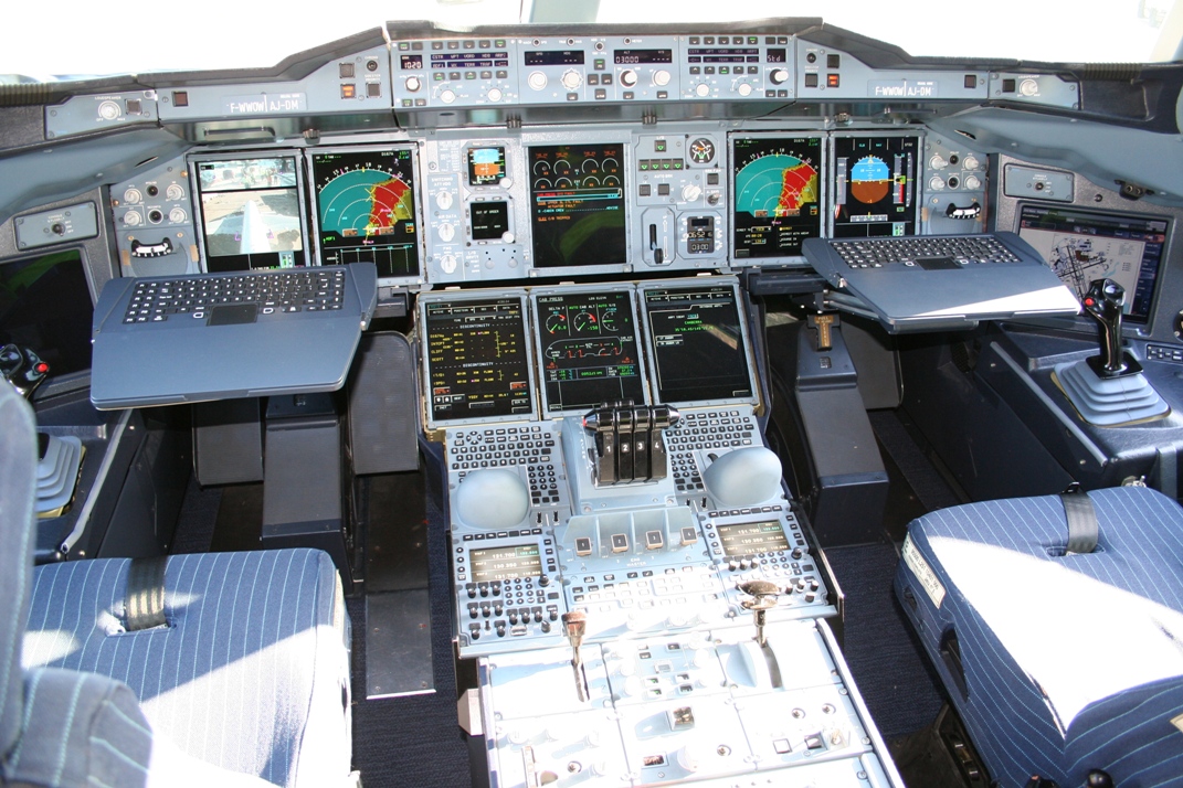 Airbus A380 glass cockpit
Glide ratio:
When flown at a constant speed in still air a glider moves forwards a certain distance for a certain distance downwards. The ratio of the distance forwards to downwards is called the glide ratio. The glide ratio (E) is numerically equal to the lift-to-drag ratio under these conditions; but is not necessarily equal during other manoeuvres, especially if speed is not constant. A glider's glide ratio varies with airspeed, but there is a maximum value which is frequently quoted. Glide ratio usually varies little with vehicle loading however, a heavier vehicle glides faster, but maintains its glide ratio.

Glide ratio (or "finesse") is the cotangent of the downward angle, the glide angle (γ). Alternatively it is also the forward speed divided by sink speed (unpowered aircraft):

Glide number (ε) is the reciprocal of glide ratio but sometime it's confused.
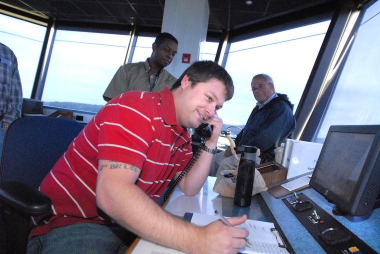
Ground Control,GND:
Ground Control is responsible for the airport "movement" areas. These include all taxiways, holding areas, and some manoeuvring areas or intersections where aircraft arrive after having left the runway or the departure gates. Responsibilities and working areas allotted to each air traffic controller are clearly defined in local documents and agreements specific to each airport. Aircraft and vehicles changing their position within these movement areas, are required to have clearance from the ground controller. This is normally done via radio contact, but there may be special circumstances where other methods are used, such as communication through visual signals.
Efficient ground control is vital to smooth airport operations because, on top of his most important mission which is to ensure the safety of ground movements, the ground controller is responsible for optimising the order in which the aircraft are sequenced to depart at the runway threshold and this in order to accelerate the take-off rhythm. Some very busy airports dispose of electronic systems designed to detect and identify aircraft and vehicles on the ground. The ground controller uses them as an additional tool to control ground traffic, particularly at night or in poor visibility. These advanced systems can display a detailed overview of the ground operations, where every vehicle detected by the radars is identified by a data blocks. Furthermore, computerized alarm signals warn the ground controller of every potential danger. In addition, the AMS (Airport Movement System), developed by Belgocontrol, supplies the air traffic controllers with all relevant information regarding the controlled aircraft in a concise and efficient manner.
It gets a lot more challenging in the high traffic areas like New York & New Jersey which have 3 major airports within very close proximity of each other. The same case on the west coast with San Francisco, Oakland & San Jose international airports.These are some of the worlds most congested airspaces and managing them is a job for a skilful few. The enroute & tower controllers guide the airplanes safely and as fast as possible to their destination airports. Once the airplane has landed, travellers feel happy about reaching their destination and they are in a big hurry to get off the plane. But they can’t do so unless the airplane has reached its gate and parked safely.
Guiding the plane to the gate is the responsibility of Ground Control. The Tower control ensures that the airplane has landed safely, guides it away from the active runway via taxiways and hands them to Ground Control. The time it takes to reach the gate after the plane has landed depends on a lot of factors, primary being the traffic or the number of planes already on the ground moving around the airport either for a departure or heading towards a gate. The more the number of planes the longer it will take. The airport and taxiway layout also play a major role in how long the taxi times are. Airports with straight taxiways and less turns see aircraft reaching higher taxing speed than airports which have more turns. The taxing times for departing airplanes is also highly dependent on the take-off queue size.
Guiding planes on the ground is as challenging as in the air. The planes have to remain on their taxiways and away from active runways. In the air, when 2 planes come close to each other, the TCAS (Traffic Collision Avoidance System) alerts the pilots and they can take heavy evasive action like diving, ascending, turning left or right to avoid the collision. The same cannot be done on the ground. If the planes leave their taxiways suddenly they are at a high risk of being grounded. Yes, grounded. The wheels of the planes can get stuck in the mud or can burst if they go over a sharp object. Worst, the plane can collide with another plane which can be catostropic. The Ground Controller needs to ensure that such a situation never occurs and he or she must keep the planes moving. Guiding the departing planes to the runways and arriving ones to their gates ensures that the airport stays operational.
Go around:
Some pilots tend to think that a go-around is a last-resort emergency procedure that they hope to never need to do. In fact, pilots should be so proficient with go-around skills that they have total confidence in doing them, and thus are prepared to initiate a good go-around instantly at any point in an approach.
The go-around is not strictly an emergency procedure. It is a normal maneuver that may at times be used in an emergency situation. Like any other normal maneuver, the go-around must be practiced and perfected.
There are many factors that can contribute to unsatisfactory landing conditions including air traffic control requirements, unexpected appearance of hazards on the runway, overtaking another airplane, wind shear, wake turbulence, mechanical failure and/or an unstabilized approach, and sometimes just finding yourself trying to ‘keep up’ with the airplane in a busy situation.
Although the need to discontinue a landing may arise at any point in the landing process, the most critical go-around will be one started when very close to the ground. Therefore, the earlier a condition that warrants a go-around is recognized, the safer the go-around/rejected landing will be.
The go-around maneuver is not inherently dangerous in itself. It becomes dangerous only when delayed unduly or executed improperly.
A good go-around maneuver starts with your familiarity of the three cardinal principles of the procedure: power, attitude, and configuration.
Power
Power is the pilot’s first concern. The instant the pilot decides to go around, full or maximum allowable takeoff power must be applied smoothly and without hesitation, and held until flying speed and controllability are restored.
Applying only partial power in a go-around is never appropriate. The application of power should be smooth and positive. Abrupt movements of the throttle in some airplanes could cause the engine to falter. Carburetor heat should be turned off for maximum power.
Attitude
Attitude is always critical when close to the ground, and when power is added, a deliberate effort on the part of the pilot will be required to keep the nose from pitching up prematurely.
The airplane must be maintained in an attitude that permits a buildup of airspeed well beyond the stall point before any effort is made to gain altitude or to execute a turn. Raising the nose too early may produce a stall from which the airplane could not be recovered if the go-around is performed at a low altitude.
A concern for quickly regaining altitude during a go-around produces a natural tendency to pull the nose up. The pilot executing a go-around must accept the fact that an airplane will not climb until it can fly, and it will not fly below stall speed.
In some circumstances, it may be desirable to lower the nose briefly to gain airspeed. As soon as the appropriate climb airspeed and pitch attitude are attained, the pilot should “rough trim” the airplane to relieve any adverse control pressures. Later, more precise trim adjustments can be made when flight conditions have stabilized.
Configuration
In cleaning up the airplane during the go-around, the pilot should be concerned first with flaps and secondly with the landing gear (if retractable).
When the decision is made to perform a go-around, takeoff power should be applied immediately and the pitch attitude changed so as to slow or stop the descent.
After the descent has been stopped, the landing flaps may be partially retracted or placed in the takeoff position as recommended by the manufacturer. Caution must be used, however, in retracting the flaps. Depending on the airplane’s altitude and airspeed, it may be wise to retract the flaps intermittently in small increments to allow time for the airplane to accelerate progressively as they are being raised. A sudden and complete retraction of the flaps could cause a loss of lift resulting in the airplane settling into the ground.
Unless otherwise specified in the AFM/POH, it is generally recommended that the flaps be retracted (at least partially) before retracting the landing gear.
When takeoff power is applied, it will usually be necessary to hold considerable pressure on the controls to maintain straight flight and a safe climb attitude since the airplane has been trimmed for the approach
The addition of power will tend to raise the airplane’s nose suddenly and veer to the left. Forward elevator pressure must be anticipated and applied to hold the nose in a safe climb attitude. Right rudder pressure must be increased to counteract torque and P-factor, and to keep the nose straight. The airplane must be held in the proper flight attitude regardless of the amount of control pressure that is required.
The landing gear should be retracted only after the initial or rough trim has been accomplished and when it is certain the airplane will remain airborne
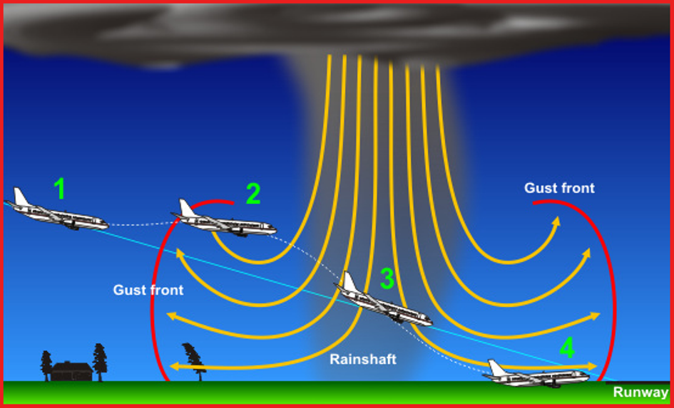
Gust front:
The outflow winds known as "outflow boundary" is also known because of convective formations (eg. A thunderstorm or cumulonimbus single chain) precipitation caused by katabatic gust wind action on the ground and in the radial direction runs cold air on the ground leading edge of the border. The existence of the surrounding formations is usually low-level glomerules, or sometimes roller clouds edge clouds may indicate when such a temperature suddenly decreases, the atmospheric pressure is rising. On the surface, the wind suddenly resurrection marks the outflow winds transits. The outflow winds will develop then the strong air downwash a result, when the descending vertically at high speed air column hits the ground, and there proceed can not, so we all directions sprawled horizontally continues his path, causing strong as 180 km / h horizontal wind of the 300-600 meters from the ground level.
If the downwash formed in front of the aircraft, we will detect this from the fact that all of a sudden we get a very strong horizontal wind-face without any justification. If we are not sufficiently prepared for this, then, in this case the crew pulls the throttle a little bit and lifts the nose. Yes, but since this slice was observed due to downwash caused by the vertical sprawl, so we'll probably go to a private katabatic air while flying over column is coming soon! If you avoided a lot of luck, it is a vertical column of air will be behind us, so we will start to blow from the back of strong winds spreading, which then causes a sudden decrease in lift on the wing. Countries near him so he can "sit" on the plane to the track in front of several hundred meters to the ground plane can achieve quite considerable vertical speed. So in respect of the flight we face in a very dangerous phenomenon.

Head-up display, HUD:
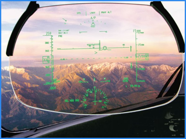
The basic and dual head-up displays promote “eyes out of the flight deck” flying for both pilots.
The flight deck of the new 787 Dreamliner introduces new technologies to help pilots work more efficiently and safely while maintaining significant operational commonality with previous generations of Boeing airplanes.
Dual head-up displays (HUD) (Boeing 787 Dreamliner) projects an image onto a glass combiner mounted in front of the pilots’ eyes (see fig. 5). It displays flight information so pilots can look outside the flight deck, scanning for traffic or flying an approach, and simultaneously view primary flight instruments. The dual HUDs enhance safety in all phases of flight, in both good or poor visibility. HUDs also enable lower visibility takeoff minimums by integrating with the navigation radios and flight management system to provide low visibility takeoff runway centerline guidance. The dual HUDs allow the first officer to be proficient in HUD use when transitioning to captain.
Tailwind, Headwind and Crosswind:
Observe the three planes in the animation below. Each plane is heading south with a speed of 100 mi/hr. Each plane flies amidst a wind which blows at 20 mi/hr. In the first case, the plane encounters a tailwind (from behind) of 20 mi/hr. The combined effect of the tailwind and the plane speed provide a resultant velocity of 120 mi/hr. In the second case, the plane encounters a headwind (from the front) of 20 mi/hr. The combined effect of the headwind and the plane speed provide a resultant velocity of 80 mi/hr. In the third case, the plane encounters a crosswind (from the side) of 20 mi/hr. The combined effect of the headwind and the plane speed provide a resultant velocity of 102 mi/hr (directed at an 11.3 degree angle east of south). These three resultant velocities can be determined using simple rules of vector addition. In the case of the crosswind, the Pythagorean Theorem and SOH CAH TOA are utilized to determine the magnitude and the direction of the resultant velocity.
All three types of wind great impact on the aircraft. The head wind like it is, "head wind" in the name, ie against blows. A tailwind, "tail wind" that is blowing from behind. The cross wind, blowing the side of the aircraft. Therefore limits (wind speed limits) provided by the aircraft manufacturer, to ensure safe take-off, and to all aircraft types. As an example, a Boeing 777-inch type, landing, the maximum allowable tailwind of 15 knots (knots) or the maximum permitted cross wind, 38 knots. A tailwind require a longer runway, while a cross wind makes it difficult to maneuver the aircraft to land. The head wind, however, required an aircraft for landing because it lowers the aircraft landing speed, so a shorter runway is needed and less brake pad wear, so the control tower at all times when the aircraft landing brewing, landing head wind direction has been entered.
Health effects of aviation:

Complaints: One in five people say plane air has made them ill
Approximately 1 billion people travel each year by air on the many domestic and international airlines. A global increase in air travel, as well as a growing aged population in many countries, makes it reasonable to assume that there will be a significant increase in older passengers and passengers with illness.
Aerotoxic syndrome
More than one in five plane passengers believe they have become ill because of poor air quality on board planes. A new study found 23 per cent of people believe they have been affected by 'aerotoxic syndrome' following high-profile claims by cabin crew against airlines.
At the altitude at which commercial planes fly, humans cannot breathe independently because of the air pressure so compressed air is drawn from the plane's engines and directed into the cabin. It may become apparent that significant numbers of the general public may have been affected, too - especially business people and other regular fliers.
Stresses of Flight
Modern commercial aircraft are very safe and, in most cases, reasonably comfortable. However, all flights, short and long haul, impose stresses on all passengers. Preflight, these include airport tumult (e.g., carrying baggage, walking long distances, and flight delays). Inflight stresses include lowered barometric and oxygen pressure, noise and vibration (including turbulence), cigarette smoking (banned on most airlines today), erratic temperatures, low humidity, jet lag, and cramped seating. Nevertheless, healthy passengers endure these stresses which, for the most part, are quickly forgotten once the destination is reached. In general, passengers with stable medical conditions usually
arrive at the destination airport none the worse. However, there is always the potential that some passengers, particularly those with unstable illness, may become ill during or postflight due to these stresses. A brief review of these stresses follows.
The primary difference between the aircraft environment and the ground environment relates to the atmosphere. Contrary to popular belief, modern aircraft are not pressurized to sea level pressure. Indeed, on most flights the cabin altitude will be between 6,000 and 8,000 ft. (1,828m and 2,438m) even though the aircraft is flying at much higher altitudes. In other words, on most flights, it is as if you are on top of a hill or small mountain. This imposes two stresses on the body: less oxygen; and, expansion of gases in the body cavities. First, with a reduced barometric pressure, there is a decrease in oxygen pressure. However, because of the characteristics of hemoglobin, the chemical in the blood that carries oxygen throughout the body, it remains 90% saturated with oxygen even at the cruising cabin altitude. (At sea level it is about 97% saturated.) Although most passengers can normally compensate for this small decrease in saturation, this may not be true for individuals with heart, lung, or certain blood diseases.
Furthermore, an increase in cabin altitude will cause gases in our body cavities (abdomen, middle ear behind the ear drum, sinuses) to expand as much as 25%. This can cause problems in the abdomen (bloating or stomach cramps), ears (a crackling sensation or ear block), and respiratory tract/sinuses that will be described later.
Although there is always some degree of vibration and aircraft turbulence, it is usually very mild. Nevertheless, passengers are always well advised to keep their seat belts secured because there is always the chance of moderate or severe turbulence that could cause injury. Severe turbulence is sometimes unpredictable and may be encountered even on clear days in excellent weather. Today’s airplanes have very low cabin humidity, usually ranging from 5-15%. This is unavoidable because air is drawn into the cabin from the outside and at high altitude it is completely devoid of moisture. As a result, there can be a drying effect on airway passages, the eyes (particularly under contact lenses), and the skin. However, the body’s protective mechanisms prevent dehydration and there is no harm to health.
Jet lag occurs when crossing multiple time zones. Our body clock, which controls hormone levels, is synchronized to the day/night cycle where we started. When we travel long distances in a matter of hours, we will arrive in another time zone, yet our body is still functioning as if it were in the time zone at the point of origin. This results in symptoms, such as fatigue and sleep disturbances that are well known to travelers. Crossing time zones may not only be an annoyance for well passengers, but it can also complicate the timing of medication dosages such as insulin (See Jet Lag and Diabetes sections).
On most flights, regardless of aircraft type, some passengers may be seated in a small, cramped space. This can be uncomfortable and it also reduces the opportunity to get up, stretch, and walk about the cabin. Sitting for long periods is tolerable for most passengers, but for some there is the potential for ankle swelling, cramps, and other circulatory problems. Of particular concern is blood clot formation causing deep venous thrombosis, although there is no evidence that this condition is caused by cramped seating.
Medical Evaluation
As stated above, the vast majority of travelers can fly quite safely. If a passenger has significant preexisting illness or an unstable medical condition, a physician should be consulted before planning to travel by air. This is particularly true for those with heart or lung disease including angina pectoris, congestive heart failure, myocardial infarction (heart attack), asthma, and emphysema. Other significant illnesses would include a history of deep venous thrombosis (blood clots), seizure disorder, stroke, and diabetes. In such cases, your physician might want to do a preflight evaluation. Vaccination and other travel health requirements should also be checked well in advance of travel abroad.
If the physician has fully reviewed the prospective traveler’s condition and there is any question regarding the suitability to fly or any special requests for assistance, the airline should be contacted well ahead of travel.
Airline Special Services
With increased attention to passengers with disabilities, many special services are offered on major air carriers. For example, special meals are generally available. In addition, wheel chairs and trolley service within the airport can be requested. Finally, early boarding is usually available to passengers with ambulatory difficulties.
As more passengers use air travel for business or leisure purposes, a growing demand for inflight medical oxygen can be expected. Some airlines will provide oxygen (for a fee), while others will not. The availability and costs will vary from airline to airline worldwide, each subject to its own national and company policies. Hence, passengers who require medical oxygen should contact the airline as far in advance of their journey as possible in order to make proper arrangements. Passengers should be cautioned that those airlines that do provide oxygen usually only do so inflight. If oxygen is also required in the airport preflight or while waiting for connections, arrangements can sometimes be made with oxygen vendors. Therefore, a traveler cannot always count on having oxygen continuously available from point of origin to destination.
Passengers must also be aware that in many countries, airlines volunteering to provide this service are required to provide the oxygen for safety and security purposes. Passengers are prohibited from bringing on board their own oxygen supply procured from an outside source. Use of the emergency drop-down masks for medical oxygen is also prohibited by most airlines, as these are only to be used for inflight emergencies, such as loss of cabin pressurization. (Some airlines do carry a very limited supply of oxygen for use in the event of an unexpected inflight medical emergency.)
With respect to use of stretchers for ill passengers, each airline has its own policy. Those that provide this service may require the purchase of as many as eight seats and that an attendant travel with the passenger. Most airlines, if not all, require use of their own stretchers in order to conform with regulatory safety specifications.
Inflight Medical Care
Every airline in the world has some capability to render emergency medical care inflight. All have medical kits of varying sophistication and flight attendants with varying training who should be capable of rendering first-aid and basic cardiopulmonary resuscitation (CPR). Policy regarding contents of the medical kit, training of the crew, and treatment of passengers is at the discretion of each nation and its airline(s). U.S. commercial carriers operating under Federal Aviation Administration (FAA) regulations carry a required first-aid kit and a medical kit (with a small number of medications). On international flights, an expanded medical kit may be available with additional medications. It cannot be overemphasized that these medical kits are only for emergency use and not for routine medical care.
Defibrillators (AEDs) form part of the chain of treatment of cardiac arrest. They will be required on all U.S. air carriers by July, 2004. (Many airlines are already carrying AEDs.) A growing number of airlines around the world are also already carrying onboard AEDs to treat passengers who develop cardiac arrest.
Commercial air carriers train their flight attendants to recognize common symptoms of distress and to respond to medical emergencies with first-aid, basic resuscitation techniques, and the use of emergency medical oxygen. The cabin crews may ask for assistance from onboard medical providers and will release the medical kit to providers with appropriate credentials.
In those circumstances when a medical provider is not available, many commercial carriers have the capability to contact emergency medical support through air-to-ground communications. The ground medical support may be provided through airline personnel or by contract to a medical consultant. In this way, medical guidance may be relayed to the onboard physician or cabin crew. On occasion, a seriously ill passenger necessitates the need to divert to an alternate airport for an unscheduled landing. Some carriers maintain a database of medical facilities available at a variety of domestic and international landing sites and can recommend the nearest appropriate emergency facility. The carrier will usually arrange for medical support to meet the aircraft on landing.
Infectious Diseases
Because the aircraft cabin is a confined space and flights may be of many hours duration, there is the risk of a contagious disease being passed from one passenger to another. This can occur when an infected passenger releases organisms into the air by breathing, coughing or sneezing. The risk of such person-to-person contact of course is much greater for those passengers sitting next to or very near the passenger with the illness. Therefore, the risk of transmission of illness in an aircraft is no different from in any confined space including a room, office, train, or bus.
There is no evidence that organisms pass from one person to another through the aircraft ventilation system. Although in newer aircraft 50% of the air in the cabin is recirculated (the other 50% is outside air), it passes through highly efficient filters that remove bacteria, fungi, and most viruses.
Passengers are further protected because of the design features of the ventilation system. Inflow and outflow ducts are located in every row (in the ceiling and floor) thereby avoiding the mixing of air throughout the cabin. This is called radial air flow. Therefore, if a passenger does have a contagious disease, only passengers in the immediate vicinity would potentially be at risk. Other passengers would be protected because of effective filtration and radial air flow of the ventilation system.
Nevertheless, there have been some incidents of disease transmission inflight. These include the flu, measles, and tuberculosis (TB). All were thought due to person-to-person transmission. Because the airlines cannot be expected to screen passengers for illness, the best prevention is postponement of air travel for anyone with a contagious disease, particularly a serious one such as TB. Therefore, out of consideration for others, passengers with illness should defer travel in any mode of public transport until well. If there is any question, a physician should be consulted.
Cabin Air Quality
Today’s modern aircraft require fuels, hydraulic fluids, oils, and other chemicals in order to operate. Most of these chemicals can cause a wide array of symptoms if exposures are in high enough concentrations for a long enough time. Because passengers and crew have complained of symptoms that they attribute to these substances, a number of studies have been conducted over the past 10-15 years.
In general, these studies have consistently revealed levels of organic substances, carbon monoxide, carbon dioxide, and airborne particles in the cabin air well below regulatory standards and below those encountered in offices, the street, or subway.
One exception is ozone, a substance found naturally in the atmosphere at altitudes where most commercial aircraft fly. It enters the cabin with outside air that is used for cabin ventilation. Ozone is a respiratory system irritant and can cause chest tightness, coughing, and shortness of breath if exposure occurs at high enough concentrations. In general, low levels have been found in aircraft cabins although, in several instances, levels were measured slightly exceeding regulatory standards. Most aircraft flying at altitudes and latitudes where high ozone concentrations are encountered now have ozone converters which break down the ozone before it reaches the cabin.
In summary, studies to date show no evidence that aircraft cabin air quality is unhealthy nor is there any epidemiological evidence linking cabin air quality with illness.
Deep Venous Thrombosis
(Blood Clots)
As a result of expanding worldwide air travel, hospitals close to international airports occasionally receive patients with symptoms typical of deep venous thrombosis (DVT) that may have started before flight, inflight, on arrival, or even days after arrival. This is a blood clot, usually in the leg, that can cause pain and swelling. Clots in the legs are not serious in themselves, but occasionally they break off and travel to the lungs (called pulmonary embolism) causing chest pain and shortness of breath. This is not a common occurrence, but when it does happen, it can be life threatening. One of the causes of DVT is believed to be prolonged immobilization, such as sitting for many hours at a time, particularly in an individual with preexisting risk factors.
Prolonged immobilization can occur not only in an airplane, but also in a car, train, or bus (or in an office or theater for that matter). There is no scientific evidence of a particular link with air travel itself. Consequently, the illness is best referred to as traveler’s thrombosis.
It should be understood that passengers may be immobilized for long periods whether in economy, business, or first-class sections. Although healthy individuals may develop DVT, those with underlying risk factors such as cancer, coronary artery disease, certain blood diseases, a history of blood clot formation, and pregnancy are at higher risk.
In order to minimize the risk of traveler’s thrombosis, the following is recommended for all travelers:
• Do not place baggage underneath the seat in front of you because that reduces the ability to move the legs.
• Exercise the legs by flexing and extending the ankles at regular intervals while seated.
• Walk about the cabin periodically on longer duration flights and when flight conditions permit.
• Do not sleep in a cramped position and avoid the use of sleep aids.
• Drink adequate amounts of water and fruit juices to maintain good hydration. Avoid or minimize dehydrating drinks such as alcohol or caffeinated beverages.
If there are risk factors as mentioned above, other preventive measures as well should be considered for you by your physician. This might include compression stockings and/or anticoagulant (blood thinners) medication.
Obstetrics And Pediatrics
The commercial aircraft environment is not generally considered hazardous to the normal pregnancy. Furthermore, there are no data to suggest that the commercial flight environment increases miscarriage risk. At normal operating altitudes, there is adequate oxygen for the pregnant traveler as well as her fetus.
However, certain precautions are advisable. With increasing altitude, there is gas expansion in the abdomen that could cause discomfort such as bloating. For this reason, it is prudent to avoid gas producing foods a few days before a scheduled flight. In addition, air travel can cause motion sickness. Consequently, the nausea and vomiting that occasionally occur in early pregnancy may be increased during flight. The managing physician may prescribe medication for those with such difficulties.
Aircraft often encounter turbulent air, sometimes unexpectedly. Pregnant travelers, therefore, should keep their seat belts fastened continuously while seated. The belt should be worn snugly over the pelvis or upper thighs, thus reducing the potential for injury of abdominal contents. Walking about the cabin inflight should be done with some caution to avoid falling or injury.
For women with a completely normal pregnancy, it is still advisable not to travel by air after the 36th week. This is just precautionary in case the due date was miscalculated or labor begins prematurely. The airplane is not the place for a delivery. If a pregnant woman decides to travel after 36 weeks, most airlines require a note from the managing obstetrician attesting that the patient is not in labor and has no complications. Pregnant women with complications such as bleeding, pain, or a history of premature delivery should not fly.
The aircraft environment is generally not a problem for healthy children. However, as the aircraft ascends and descends, there can be pain in the ears due to pressure changes causing crying. To minimize this, it is helpful to have a baby nurse a bottle, breast, or suck on a pacifier particularly during descent. This will help equalize the air pressure in the middle ear. Children with upper respiratory infections and congestion should avoid flying, but if they must, they may be given nasal decongestants, as prescribed, 30 minutes prior to descent.
Decompression Sickness (Bends)
Scuba diving has become a popular sport with thousands of people taking diving vacations. Because most divers return home by air, the relationship between diving and flying must be appreciated. Decompression sickness is caused by nitrogen bubbles forming in the blood or body fluids whenever one goes from a high pressure environment to a low pressure environment. This can happen when surfacing from a dive or going to altitude in an airplane. The risk of decompression sickness is greatly increased if one flies too soon after diving.
The most common symptoms are joint and/or muscle pain (commonly known as bends). However, these bubbles can cause much more serious illness with symptoms of stroke and collapse of the cardiovascular system. Because the latter are potentially fatal, it is advisable to reduce the risk by avoiding flying as a passenger for 12-24 hours after the last scuba dive.
Peanut Allergy
Many people suffer from peanut allergy. It can cause mild symptoms such as a rash or itching, but it can also cause severe and even life- threatening reactions with shortness of breath, wheezing, and circulatory collapse. Consequently, individuals with a known peanut allergy should refrain from eating them for life.
Because peanuts are often served to airline passengers, there is concern among the traveling public. Some strongly urge the airlines to stop serving then altogether. However, the actual risk to passengers is believed to be very low for several reasons. First, there are only rare reports in the medical literature describing a passenger reaction inflight. If it were a common problem, more reporting would be expected. Second, allergic reactions to peanuts almost always occur after eating them. It would be highly unlikely (although possible) for a reaction to occur by inhaling airborne peanut dust released from the package of a nearby passenger.
Nevertheless, many airlines no longer serve peanuts, and passengers who have special concerns may be accommodated by some airlines by offering seats in a peanut free row. In any event, no airline can guarantee the flight will be peanut free because some passengers might bring their own. Asthma and emphysema require special consideration. Those with asthma that is unpredictable, severe, or which has required recent hospitalization should not travel by air. Any asthmatic who does travel by air should hand carry onboard all asthma medications, particularly inhalers for rapid relief of symptoms. Because the air in commercial aircraft is very dry, it is important to keep well hydrated at all times. Be sure to drink sufficient amounts of water (not alcohol or caffeine-containing beverages) during flight.
Travelers with emphysema may have low blood oxygen levels. Therefore, preflight evaluation as described above is extremely important and will aid the physician in advising you. Medical oxygen therapy during flight may be required. Also, medication should be available in carry-on luggage. In some cases, other means of travel may be advisable.
Alcohol
Use caution if you decide to drink alcoholic beverages when traveling by air. Alcohol can dehydrate you and will interfere with your ability to sleep. It has also been implicated in recent incidents of “air rage.” Consequently, it is most prudent to avoid or at least minimize alcohol consumption during air travel.
Motion Sickness
Although motion sickness is less common with jets than with propeller-driven aircraft, it may occur, particularly in susceptible individuals. If you think you might require medication, consult your physician. For those susceptible to motion sickness:
• Request a seat over the wing.
• Schedule flights on larger airplanes.
• Request a window seat (and gaze at the horizon).
• Direct cool, ventilated air onto the face.
• Avoid excess liquids and gas producing foods.
• Avoid alcohol for 24 hours prior to flight and inflight.
Heart Disease
Commercial aircraft cabins are usually pressurized to altitudes between 6,000 and 8,000 ft. depending upon the actual altitude of the airplane. The Federal Aviation Administration (FAA) and Joint Aviation Authorities (JAA) allow a maximum of 8,000 ft. At this altitude the oxygen supply in the air is decreased with a corresponding decrease in the oxygen carried in the blood. In general, reasonably healthy individuals can easily tolerate this because the body is able to compensate by increasing the heart rate and respiratory rate. However, this may not be true for those with significant heart disease. This includes frequent angina , heart failure, recent heart attack, and disease of the heart valves. In some cases, air travel may have to be deferred and in others medical oxygen may be required inflight. Consequently, patients with significant heart disease should consult their physician if contemplating air travel. The physician, in turn, must exercise clinical judgment in formulating recommendations.
The following are some specific travel recommendations for heart patients:
• Carry sufficient quantities of cardiac medications for the entire trip and keep in carry-on luggage.
• Keep a separate list of medications including name of prescribing physician with phone number, dosing intervals, and tablet size in the event that medications are lost.
• Adjust dosing intervals in order to maintain dosing frequency if crossing time zones.
• Be sure all medications are taken on schedule.
• Carry a copy of most recent ECG.
• Carry a pacemaker card if a pacemaker patient.
• Contact the airline concerning needs for special diet, medical oxygen, or a wheelchair
• Consider curbside baggage check-in.
• Limit walking around, especially at altitude.
Ear Nose And Throat
Passengers traveling by aircraft experience changes in air pressure during flight. Before takeoff, cabin pressure equals the air pressure at ground level. After
16
takeoff and during climb to cruising altitude, the cabin pressure in commercial airliners is allowed to drop until it reaches the equivalent of the air pressure at 8,000 feet (2432 meters). Cabin pressure is maintained at this level, even if the aircraft flies at a much higher cruising altitude. When the aircraft descends, cabin pressure rises until landing when it again equals the pressure on the ground.
As a result of these pressure changes during ascent, air must be able to flow freely from the middle ear (the space behind the ear drum) to the outside by way of the eustachian tube and from the sinuses to the outside by way of passageways to the nose. On descent, the opposite must occur with air flowing in the reverse direction from the outside into the middle ear and sinuses. In short, this is necessary in order to equalize the air pressure in the body with that of the surrounding air. If the air pressure in the middle ear and sinuses becomes much higher or lower than the surrounding air pressure, pain, bleeding and ear drum rupture can occur.
Problems with this important air exchange are caused by a blockage of any of the passageways. Infection, such as a bad cold, allergy, bleeding, and even a tumor can cause blockage. Although problems can occur during climb to altitude, problems tend to be much more common and severe during descent to landing.
In order to avoid problems, air travel should be postponed if you have a severe allergy or respiratory infection. Further, all air travel passengers should ask their physician to teach them the techniques for equalizing sinus and middle ear air pressures. This is called a Valsalva maneuver (holding your nose shut with your fingers while forcefully exhaling against a closed mouth). It is better learned by demonstration rather than by written explanation. Chewing gum and swallowing may also help. The purpose of this is to help open all of the passageways permitting normal flow of air.
Do not forget that flying can cause air pressure equalization problems for up to several hours after the flight. Passengers may later develop pain, ear block, and general discomfort sometimes being awakened from sleep. This is virtually always due to failure to fully equalize sinus or middle ear pressures during descent and landing. In such cases, it may be necessary to see a physician.
Another problem of air travel is related to the very low humidity in the aircraft cabin. Because of the drying effects of cabin air, many air travelers may benefit from use of moisturizing nose sprays or drops.
Holding:

The primary use of a holding is delaying aircraft that have arrived at their destination but cannot land yet because of traffic congestion, poor weather, or runway unavailability (for instance, during snow removal or emergencies). Several aircraft may fly the same holding pattern at the same time, separated vertically by 1,000 feet or more. This is generally described as a stack or holding stack. As a rule, new arrivals will be added at the top. The aircraft at the bottom of the stack will be taken out and allowed to make an approach first, after which all aircraft in the stack move down one level, and so on. Air Trafic Control (ATC) will control the whole process, in some cases using a dedicated controller (called a stack controller) for each individual pattern.
One airport may have several holding patterns; depending on where aircraft arrive from or which runway is in use, or because of vertical airspace limitations.Since an aircraft with an emergency has priority over all other air traffic, they will always be allowed to bypass the holding pattern and go directly to the airport (if possible). Obviously, this causes more delays for other aircraft already in the stack.
Many aircraft have a specific holding speed published by the manufacturer; this is a lower speed at which the aircraft uses less fuel per hour than normal cruise speeds. A typical holding speed for transport category aircraft is 210 to 265 knots (491 km/h). Holding speeds are a function of aircraft weight at the point of holding. If possible, a holding pattern is flown with flaps and landing gear up to save fuel.
Entry procedures and accurate flying of the holding procedure are essential parts of IFR pilot training, and will always be tested on examination flights.
Modern autopilots, coupled with flight management systems, can enter and fly holding patterns automatically.
The entry to a holding pattern is often the hardest part for a novice pilot to grasp, and determining and executing the proper entry while simultaneously controlling the aircraft, navigating and communicating with ATC requires practice. There are three standard types of entries: direct, parallel, and offset (teardrop). The proper entry procedure is determined by the angle difference between the direction the aircraft flies to arrive at the beacon and the direction of the inbound leg of the holding pattern.
- A direct entry is performed exactly as it sounds: the aircraft flies directly to the holding fix, and immediately begins the first turn outbound.
- In a parallel entry, the aircraft flies to the holding fix, parallels the inbound course for one minute outbound, and then turns back, flies directly to the fix, and continues in the hold from there.
- In an offset or teardrop entry, the aircraft flies to the holding fix, turns into the protected area, flies for one minute, and then turns back inbound, proceeds to the fix and continues from there.
Human error:
To this day the majority of aviation accidents are attributed in some way, to some form of human error. Surprising when you consider all the effort and expense put into management, research, training and the development of new technologies such as automation. Yes, safety has vastly improved over the last 50 years, making flying one of the safest methods of getting around our planet. But still human error related accidents occur.
Definition:
Planned actions that fail to achieve their desired consequences without the intervention of some chance or unforeseeable agency.
Types of human error:
The simplest catergorisation of human error would be to split them into errors of omission or commission.
- Omission - Errors of omission occur when crew members fail to carryout a required task.
- Commision - Errors of commission occur when crew members carryout a task incorrectly or do something that is not required.
- Slips - Which occur as the result of minor errors of execution.
- Lapses - Which occur when a pilot becomes distracted and doesn’t complete a task or omits a step whilst performing it.
- Mistakes - Which occur when actions conform to an inadequate plan.
- Violations - Which occur where actions deviate from safe procedures standards or rules, be they deliberate or erroneous.
Errors in Aviation:
There are three main areas in aviation, of interest to human factors professionals and managers who wish to understand and reduce human error.
- Pilot or Flightdeck error.
- Air traffic Control error.
- Maintenance errors
Managing error in Aviation:
Early psychological researchers regarded people who erred as being less effective due to unconscious drives. A theory that tainted early research on human error. Approaches to human error rectification and management tending to centre on blame, training and quite possibly punishment.
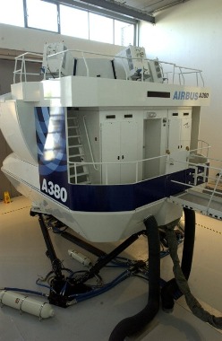
Airbus A380 simulator
Humidity of the air:
Steam is produced when the sun heats the water, such as water vapor into the air. If you prefer the water warms, more water vapor comes into the air. The warming of the atmosphere with water vapor capacity increase. The granting of humidity you have two options:
-Absolute water vapor
-Relative water vapor
Absolute water vapor: It shows that the air contains from 1 m³ how many grams of water vapor. However, this is not often used, but rather used the relative water vapor.
Relative water vapor content: Specifies% value of water vapor, at a given temperature, the air is fully saturated with water vapor in the air compared to water content. A gas turbine equipped with jet aircraft engines specifically beneficial due to the high air humidity, the engines of improvement in thermodynamic equilibrium. Lifting her power as a result of the increase in thrust, but the noise effect is deteriorating, that noisy to hear the engines at this time due to the increase in air humidity.

IAS:
The airspeed shown on the flight-deck instrument. An aneroid instrument, the airspeed indicator measures the dynamic pressure of the outside air entering a pitot tube. At sea level, and an atmospheric pressure of 1013.2 mb, and with no wind effect, the airspeed indicated is the true speed of the aircraft relative to the surface. As the aircraft climbs, the air density decreases and the indicated speed will be less than the True Air Speed (TAS). However, when it comes to controlling the aircraft, because the flight characteristics of the aircraft also alter with reduction in atmospheric density, the indicated airspeed is of greater importance than the true airspeed. This is why control speeds (e.g. V1, V2, etc) are given as KIAS (Knots Indicated Airspeed).
ILS (Instrument landing system):
The Instrument Landing System (ILS) is an internationally normalized system for navigation of aircrafts upon the final approach for landing. It was accepted as a standard system by the ICAO, (International Civil Aviation Organization) in 1947.
Since the technical specifications of this system are worldwide prevalent, an aircraft equipped with a board system like the ILS, will reliably cooperate with an ILS ground system on every airport where such system is installed.
The ILS system is nowadays the primary system for instrumental approach for category I.-III-A conditions of operation minimums and it provides the horizontal as well as the vertical guidance necessary for an accurate landing approach in IFR (Instrument Flight Rules) conditions, thus in conditions of limited or reduced visibility.The accurate landing approach is a procedure of permitted descent with the use of navigational equipment coaxial with the trajectory and given information about the angle of descent.
The equipment that provides a pilot instant information about the distance to the point of reach is not a part of the ILS system and therefore is for the discontinuous indication used a set of two or three marker beacoms directly integrated into the system. The system of marker beacons can however be complemented for a continuous measurement of distances with the DME system (Distance measuring equipment), while the ground part of this UKV distance meter is located co-operatively with the descent beacon that forms the glide slope. It can also be supplemented with a VOR system by which means the integrated navigational-landing complex ILS/VOR/DME.
Categories of operation minimums:
Category I
- A minimal height of resolution at 200 ft (60,96 m), whereas the decision height represents an altitude at which the pilot decides upon the visual contact with the runway if he’ll either finish the landing maneuver, or he’ll abort and repeat it.
- The visibility of the runway is at the minimum 1800 ft (548,64 m)
- The plane has to be equipped apart from the devices for flying in IFR (Instrument Flight Rules) conditions also with the ILS system and a marker beacon receiver.
Category II
- A minimal decision height at 100 ft (30,48 m)
- The visibility of the runway is at the minimum 1200 ft (365,76 m)
- The plane has to be equipped with a radio altimeter or an inner marker receiver, an autopilot link, a raindrops remover and also a system for the automatic draught control of the engine can be required. The crew consists of two pilots.
Category III A
- A minimal decision height lower than 100 ft (30,48 m)
- The visibility of the runway is at the minimum 700 ft (213,36 m)
- The aircraft has to be equipped with an autopilot with a passive malfunction monitor or a HUD (Head-up display).
Category III B
- A minimal decision height lower than 50 ft (15,24 m)
- The visibility of the runway is at the minimum 150 ft (45,72 m)
- A device for alteration of a rolling speed to travel speed.
Category III C
- Zero visibility
The ILS system consists of four subsystems:
- VHF localizer transmitter
- UHF glide slope transmitter
- marker beacons
- approach lighting system
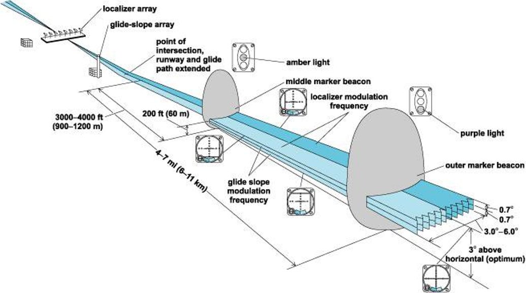
The description and placement of the individual parts of the ILS system
(figure source: http://niquette.com/books/chapsky/skypix/ILS.gif)
Ground equioment
Localizer
One of the main components of the ILS system is the localizer which handles the guidance in the horizontal plane. The localizer is an antenna system comprised of a VHF transmitter which uses the same frequency range as a VOR transmitter (108,10 ÷ 111,95 MHz), however the frequencies of the localizer are only placed on odd decimals, with a channel separation of 50 kHz. The trasmitter, or antenna, is in the axis of the runway on it’s other end, opposite to the direction of approach. A backcourse localizer is also used on some ILS systems. The backcourse is intended for landing purposes and it’s secured with a 75 MHz marker beacon or a NDB (Non Directional Beacon) located 3÷5 nm (nautical miles), or 5,556÷9,26 km before the beginning of the runway.
The course is periodically checked to ensure that the aircraft lies in the given tolerance.
Antennas of the localizer system
The transmitted signal:
The localizer, or VHF course marker, emits two directional radiation patterns. One comprises of a bearing amplitude-modulated wave with a harmonic signal frequency of 150 Hz and the other one with the same bearing amplitude-modulated wave with a harmonic signal frequency of 90 Hz. These two directional radiation patterns do intersect and thus create a course plane, or a horizontal axis of approach, which basically represents an elongation of the runway’s axis (see Fig. 1).
For an observer – a pilot, who is situated on the “approaching” side of the runway (therefore in front of the LLZ antenna system) predominates a modulation of 150 Hz on the right side of the course plane and 90 Hz on the left. The intersection of these two regions determines the on-track signal.
The width of the navigational ray can span from 3° to 6°, however mostly 5° are used. The ray is set to secure a signal approximately 700 ft (213, 36 m) wide on the borderline of the runway. The width of the ray magnifies, so at a distance of 10 nm (18,52 km) from the transmitter is the ray about 1 nm (1,852 km) wide.
The range of the localizer can be even 18 nm (33,336 km) in the 10° field from the center of the ray (on-track signal) and 10 nm (18,52km) in the field 10°÷35° from the center of the ray, because the main part of the signal is coaxial with the middle of the runway. The localizer is identified by an audio signal added to the navigational signal. The audio signal consists of letter „I“, following with a two-letter addition, for example: „I-OW“.
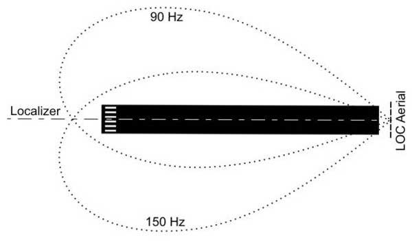
Figure 1- Radiation pattern of the localizer’s VHF transmitter
UHF descent beacon – glide slope
The transmitted signal:
The glide slope, or angle of the descent plane provides the vertical guidance for the pilot during an approach. It’s created by a ground UHF transmitter containing an antenna system operating in the range of 329,30÷335.00 MHz, with a channel separation of 50 kHz.
The transmitter (Fig. 2) is located 750÷1250 ft (228,6÷381 m) from the beginning of the runway and 400÷600 ft (121,92÷182,88 m) from it’s axis. The observed tolerance is ±0,5°. The UHF glide slope is „paired“ with the corresponding frequency of the VHF localizer.
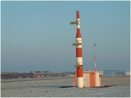
Figure 2- The UHF descent beacon draws a glide slope in the area
Like the signal of the localizer, so does the signal of the glide slope consist of two intersected radiation patterns, modulated at 90 and 150 Hz. However unlike the localizer, these signals are arranged on top of each other and emitted along the path of approach, as you can see in Fig. 3. The thickness of the overlaping field is 0,7° over as well as under the optimal glide slope.
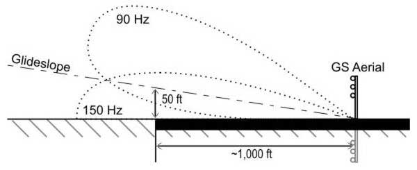
Figure 3 - The radiation pattern of the UKV descent beacon forming the glide slope
The signal of the glide slope can be set in the range of 2°÷4,5° over the horizontal plane of approach. Typically it’s a value of 2,5°÷3°, depending of the obstacles along the corridor of approach and the runway’s inclination.
False signals can be generated along the glide slope. It’s happening in multiples of the angle that‘s formed by the glide slope and the horizontal plane. The first case arises at approximately 6° over the horizontal plane. These false signals are inversive, which means that the directions to climb or descend will be swapped. A false signal at 9° will be oriented the same as the real glide slope. There are no false signals under the glide slope.
Onboard equipment
Localizer receiver
The signal is received on board of an aircraft by an onboard localizer receiver. The localizer receiver and the VOR receiver form a single unit. The signal of the localizer launches the vertical indicator called the track bar (TB). Provided that the final approach does occur from south to north, an aircraft flying westward from the runway’s axis (Fig. 4) is situated in an area modulated at 90 Hz, therefore the track bar is deflected to the right side.
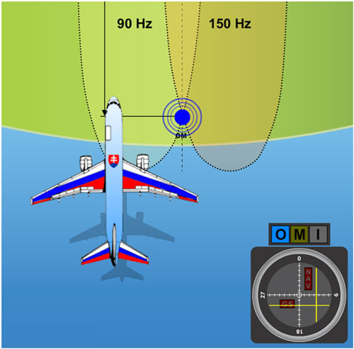
Figure 4 – A plane flying approximately along the axis of approach, however partially turned away to the left
On the contrary, if the plane’s positioned east from the runway’s axis, the 150 Hz modulated signal causes the track bar to lean out to the right side. In the area of intersection, both signals affect the track bar, which causes to a certain extent a deflection in the direction of the stronger signal. Thus if an aircraft flies roughly in the axis of approach leaned out partially to the right, the track bar is going to deflect a bit to the left. This indicates a necessary correction to the left. In the point where both signals 90 Hz and 150 Hz have the same intensity, the track bar is in the middle. Meaning that the plane is located exactly in the approach axis (Fig. 6).
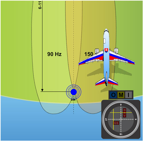
Figure 5 – A plane flying nearly in the approach axis slighlty leaned out to the right
When the track bar is used in conjunction with a VOR, a lean out of 10° to one or the other side from the signal causes a full deflection of the indicator. If the same pointer is used as an indicator of the ILS localizer, a full deflection will be induced by a 2,5° diversion from the center of the localizer’s beam. Therefore the sensitivity of the TB is roughly four times greater in the function as an indicator of the localizer as at the indication of information from the VOR.
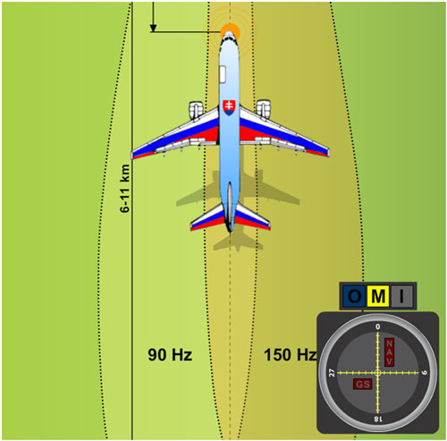
Figure 6 – A plane flying exactly in the axis of approach
In case that a red NAV bat appears in the upper right section of the onboard ILS indicator (Fig. 7), it represents that the signal is far too weak or out of the receiver’s reach and for that reason the pointer’s deflection cannot be considered to be accurate. The vertical pointer will return to the neutral position, meaning to the center of the indicator. A momentary display of the NAV bat, short deviations of the TB, or both instances happening at once can occur in the case that an aircraft flies between the receiver’s antenna and the transmitter, or some other obstacle gets into their way.
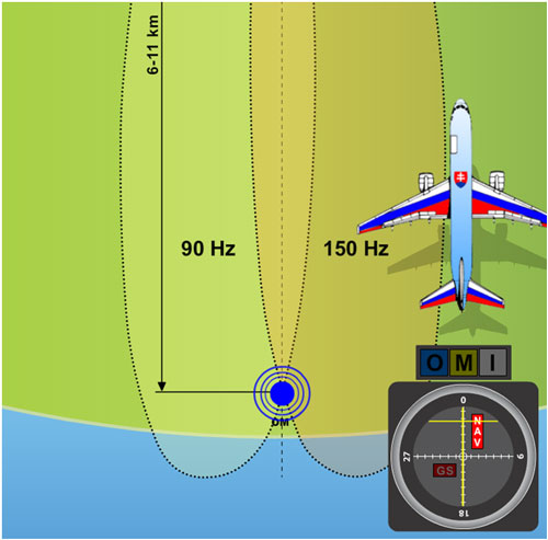
Figure 7 – A plane situated out of reach of the VKV course beacon’s signal
glide slope receiver
The glide slope’s signal is on board of a plane received by means of a UHF antenna. In modern avionics are the controls for this receiver combined with the VOR’s controls, so the correct frequency of the glide slope beacon is tuned in automatically at the instant when the localizer’s frequency is selected.
The glide slope’s signal puts the horizontal pointer of the glide slope into operation which intersects the TB, see Fig. 10 and Fig. 11. This indicator has its own GS bat which lights up whenever the glide slope beacon’s signal is too weak or the onboard receiver, hence the whole aircraft is out of the signal’s reach (Fig. 8).
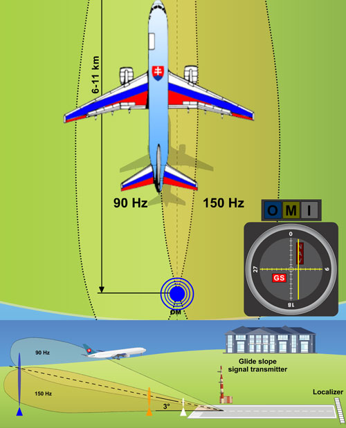
Figure 8 – An example of the displayed GS pointer notifying a diversion from the glide slope, a too weak received signal, or an obstacle on the way.
The onboard indicator of the ILS system can be used by a pilot to determine the exact position because it provides vertical as well as horizontal guiding. The case in Fig. 9 portrays both indicators in the middle, which means that the aircraft is located in the point of intersection of the course plane (horizontal) and the glide slope. The event pictured in Fig. 10 indicates that the pilot must descent and correct the flight course to the left in order to aquire the correct course and glide slope level. The case in Fig. 11 shows a necessity to ascend and adjust the flight course to the right.
With a 1,4° overlapping of the beams is the area around 1500 ft (457,2 m) wide at a distance of 10 NM (18,52 km), 150 ft (45,72 m) at a distance of 1 NM (1,852 km), and less than one foot (0,3 m) at the instant of touch down.
The apparent sensitivity of the instrument increases as the aircraft closes in to the runway. The pilot has to watch the indicator with attention so that he can keep an overlap of both needles of the pointer in the middle of the indicator. Thereby he’ll achieve a precise homing all the way to the touch down.
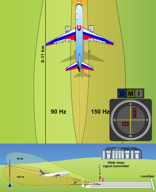
Figure 9 – Both pointers in the middle – the aircraft is located in the point of intersection of the course and descent plane.
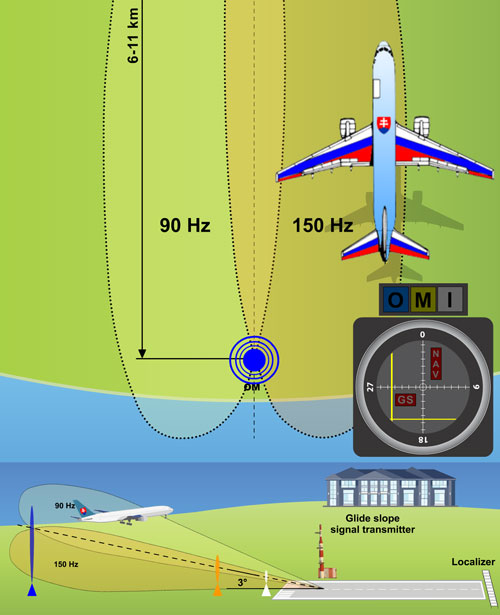
Figure 10 – A case when the aircraft is located right of the runway’s axis and too high over the glide slope.
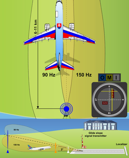
Figure 11 – A case when the aircraft is located left of the runway’s axis and too low under the glide slope.
Marker beacons
For the purpose of discontinuous addition of navigation data with the value of a momentary distance from the aircraft to the runway’s threshold, the following marker beacons are used:
Outer Marker (OM)
- The outer marker is located 3,5÷6 NM (5.556÷11.112 km) from the runway’s threshold. Its beam intersects the glide slope’s ray at an altitude of approximately 1400 ft (426.72 m) above the runway. It also roughly marks the point at which an aircraft enters the glide slope under normal circumstances, and represents the beginning of the final part of the landing approach.
- The signal is modulated at a frequency of 400 Hz, made up by a Morse code – a group of two dots per second. On the aircraft, the signal is received by a 75 MHz marker receiver. The pilot hears a tone from the loudspeaker or headphones and a blue indicative bulb lights up. Anywhere an outer marker cannot be placed due to the terrain, a DME unit can be used as a part of the ILS to secure the right fixation on the localizer.
- In some ILS installations the outer marker is substituted by a Non Directional Beacon (NDB).

The outer position marker (blue).
Middle Marker (MM)
- The middle marker is used to mark the point of transition from an approach by instruments to a visual one. It’s located about 0,5÷0,8 NM (926÷1482 m) from the runway’s threshold. When flying over it, the aircraft is at an altitude of 200÷250 ft (60,96÷76,2) above it. The audio signal is made up of two dashes or six dots per second. The frequency of the identification tone is 1300 Hz. Passing over the middle marker is visually indicated by a bulb of an amber (yellow) colour . It was removed in some countries, e.g. in Canada.

The middle marker (yellow).
Inner Marker (IM)
- The inner marker emits an AM wave with a modulated frequency of 3000 Hz. The identification signal has a pattern of series of dots, in frequency of six dots per second. The beacon is located 60m in front of the runway’s threshold. The inner marker has to be used for systems of the II. and III. category.

The inner marker (white).
Limitations
Because of the complexity of the ILS system, there are some limitations because the broadcast signal is sensitive to certain obstacles, such as buildings, hangars and surface unevenness of the terrain. The system construction is very costly.

Jet engine:
A jet engine is a machine for turning fuel into thrust (forward motion). The thrust is produced by action and reaction—a piece of physics also known as Newton's third law of motion. The force (action) of the exhaust gases pushing backward produces an equal and opposite force (reaction) called thrust that powers the vehicle forward. Exactly the same principle pushes a skateboard forward when you kick backward with your foot. In a jet engine, it's the exhaust gas that provides the "kick". Let's have a look inside the engine...
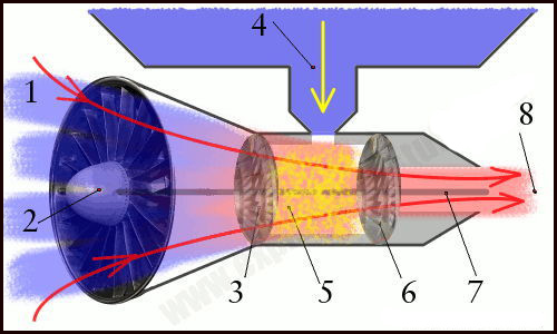
This simplified diagram shows you the process through which a jet engine converts the energy in fuel into kinetic energy that makes a plane soar through the air
1. For a jet going slower than the speed of sound, the engine is moving through the air at about 1000 km/h (600 mph). We can think of the engine as being stationary and the cold air moving toward it at this speed.
2. A fan at the front sucks the cold air into the engine.
3. A second fan called a compressor squeezes the air (increases its pressure) by about eight times. This slows the air down by about 60 percent and it's speed is now about 400 km/h (240 mph).
4. Kerosene (liquid fuel) is squirted into the engine from a fuel tank in the plane's wing.
5. In the combustion chamber, just behind the compressor, the kerosene mixes with the compressed air and burns fiercely, giving off hot exhaust gases. The burning mixture reaches a temperature of around 900°C (1650°F).
6. The exhaust gases rush past a set of turbina blades, spinning them like a windmill.
7. The turbine blades are connected to a long axle (represented by the middle gray line) that runs the length of the engine. The compressor and the fan are also connected to this axle. So, as the turbine blades spin, they also turn the compressor and the fan.
8. The hot exhaust gases exit the engine through a tapering exhaust nozzle. The tapering design helps to accelerate the gases to a speed of over 2100 km/h (1300 mph). So the hot air leaving the engine at the back is traveling over twice the speed of the cold air entering it at the front—and that's what powers the plane. Military jets often have an after burner that squirts fuel into the exhaust jet to produce extra thrust. The backward-moving exhaust gases power the jet forward. Because the plane is much bigger and heavier than the exhaust gases it produces, the exhaust gases have to zoom backward much faster than the plane's own speed.
Jet stream:
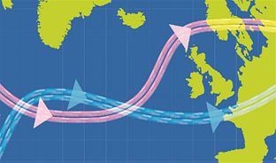
The jet stream consists of ribbons of very strong winds which move weather systems around the globe. Jet streams are found 9-16 km above the surface of the Earth, just below the tropopause, and can reach speeds of 200 mph.
The position of a jet stream varies within the natural fluctuations of the environment. They are caused by the temperature difference between tropical air masses and polar air masses. What happens in one part of the world depends on what is happening elsewhere - the atmosphere is a complete environment with numerous connections.
Waves or ripples along the jet stream can cause Atlantic depressions to deepen explosively as they are steered towards the UK, so they are very important to meteorologists.
Met Office forecasters work in one of only two centres in the world that produce weather charts for global aviation, detailing the location, height and strength of forecast jet streams and the turbulence associated with them. Trans-Atlantic aircraft take advantage of this information - this is why flights home from the USA are often much quicker than outbound flights.
Landing:
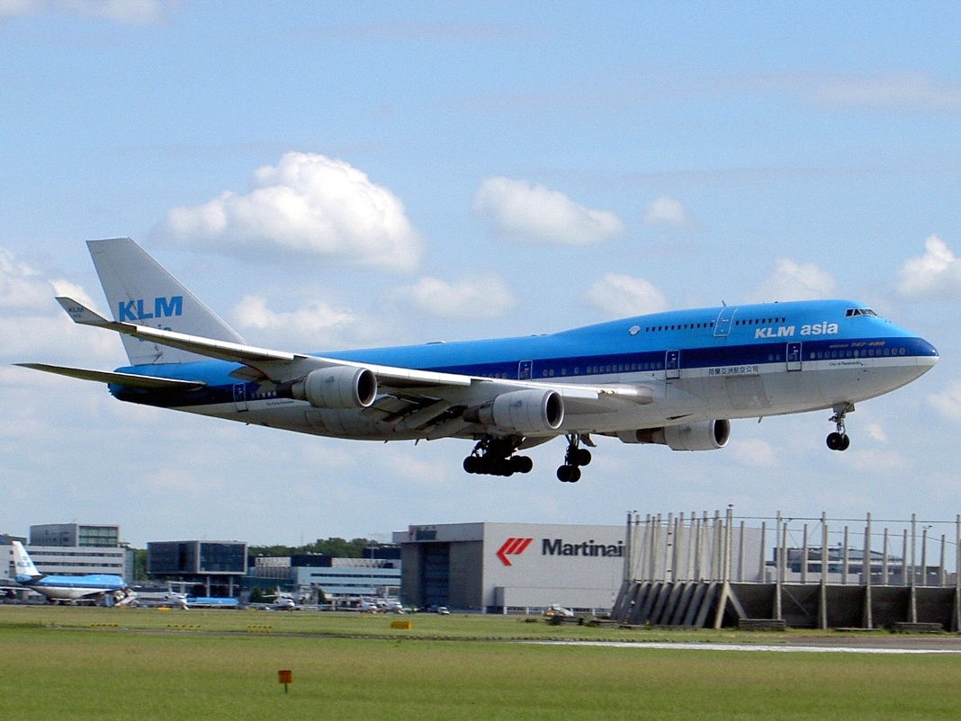
This is a seemingly simple maneuver can get the best of even the most seasoned veteran pilot, however, in many cases, especially in extreme conditions is the most critical part of the flight missions. Because of the landing maneuver is different according to types of the aircraft (Flight Operation Manual), therefore I deal with the aircraft landing in general terms.
OVERVIEW
Let's take a look at what is going on in this phase of aircraft operations.
In the figure below are shown the four prime factors that affect your aircraft in the landing configuration:
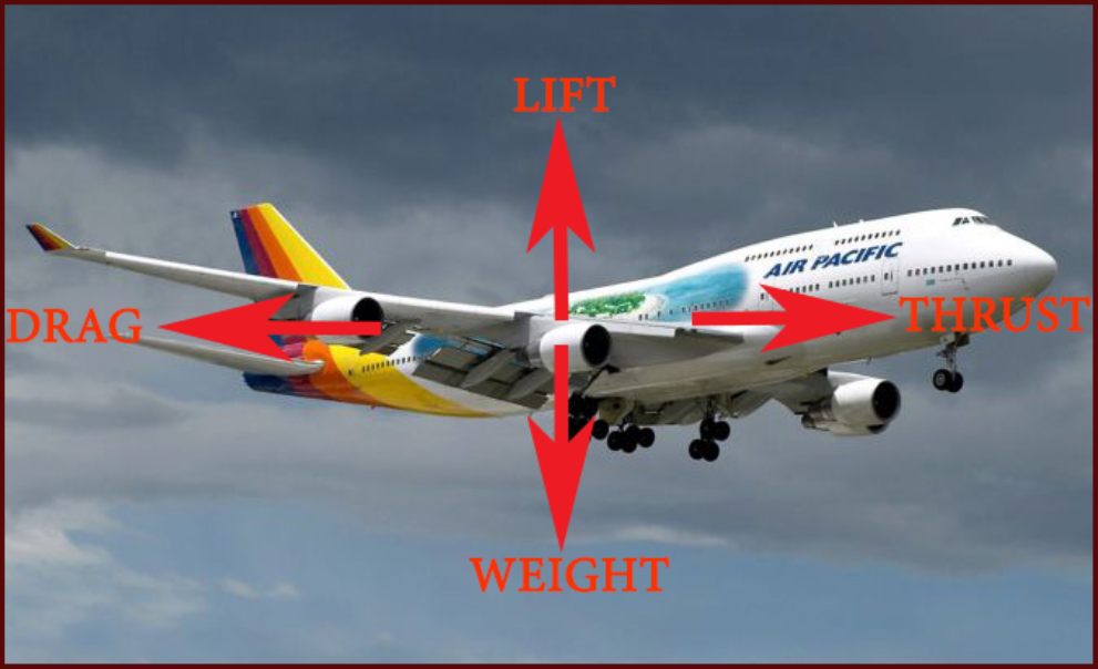
THRUST: This is your engine power.
LIFT: The "force" that opposes gravity (weight). It is produced by air flowing in an undisturbed manner over and under the wing. Available lift at slower speeds can be increased by the use of flaps.
DRAG: The opposite, naturally, of thrust. It is the resistance of the body of the aircraft and its surfaces as it moves through the air.
WEIGHT: The greater the weight, the more lift required to maintain flight.
CONTROLS AND SURFACES USED DURING LANDING
I'am going to assume that the reader has a basic understanding of how an aircraft is operated and controlled in landing flight.
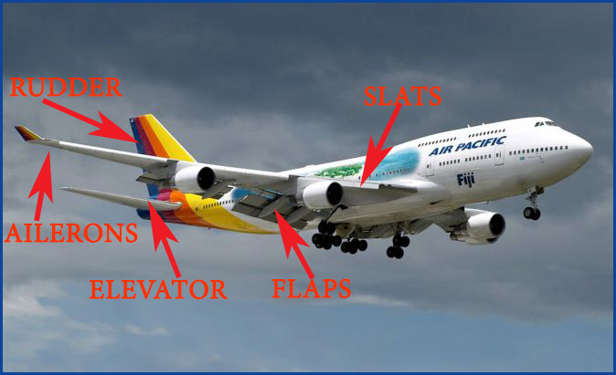
SLATS: Slats are leading edge extensions that increase the overall camber of the wing, producing more lift at slower airspeeds.
AILERONS: Ailerons control the rolling motion of the aircraft. Like all control surfaces, they become less effective as the airspeed of the aircraft decreases.
FLAPS: The "kissing cousins" of slats. These extend from the trailing edge of the wings surface. Like the slats, they increase the overall camber of the wing producing more lift at slower airspeeds.
RUDDER: The rudder controls the yaw of the aircraft, the rotation around the vertical axis.
ELEVATOR: The elevator controls the pitch of the aircraft, nose up or nose down.
THOUGHTS ON THE LANDING PHASE
The whole idea of landing an airplane is to place it where you want it on the runway. In order to do this, you as the pilot must have control over those factors that were shown in the first illustration: thrust, lift and drag. Mother Nature does Her part by furnishing the fourth item, weight (gravity). You want to have control over all facets of the operation. It's all the Oriental Yin and Yang thing. You want to go up- and down. You want to go faster- and slower and so on.
AIRSPEED
Look at the bottom of the white arc on the airspeed indicator. That speed is the stall speed with power off and flaps down- not very exact, but a start. Take that airspeed and multiply it by 1.3. For example, if the speed at the bottom of the white arc on your Speedwing is 100 knots, then that number times 1.3 yields an approach speed of 130 knots. Better yet, take you Speedwing up into the practice area and do some power off stalls with the gear and flaps down. Note the speed where the first indication of a stall is. Technically this speed is Vso, the stalling speed of the aircraft in a landing configuration. Take this number and multiply it by 1.3. That will be your approach speed.
Keep in mind that the "multiply by 1.3" is just an approximation. It will give you a starting off point that may be adjusted up or down as necessary. Without a aircraft manual listing definitive airspeeds you will have to do some "Kentucky windage" for your starting off point. If trial and error shows the speed to be high or low, adjust as necessary.
As an aside, doing practice power off stalls in the landing configuration is excellent practice. You should do this with any airplane that you are not familiar with before you practice landings. When doing your stalls, notice how the ailerons, the rudder and the elevator become decreasingly effective as you approach the stall. This is important, and critical information to you as a pilot. This "mushiness" will be your first indication of an impending stall without your ever having to look at the airspeed indicator.
ALTITUDE
How high? Well, figure that you should be about 2,000 feet above the ground when you are about five miles out from the end of the runway. This is not a hard and fast number, just an approximation.
ANGLE OF APPROACH
What angle to use for landing on the runway? If you had a chance to go up with an instructor, he would give this input to you until you had a clear mental picture of where your airplane should be during the approach to a landing. Unfortunately, in a simulator every flight is a solo flight, including your first one.
One way to solve this dilemma is to set up the simulator for practice landings at a runway that has an ILS (Instrument Landing System). Tune in the appropriate frequency and watch the Glide Slope indicator as you practice your approaches. If the "bar" goes up, you are too low, if the "bar" goes down, you are too high. Get a mental picture of how this approach angle looks with relationship to your altitude and distance from the runway.
Another way is to go to an airport that has a runway with VASI (Visual Approach Slope Indicator). There are a variety of styles, but in essence if the far lights are red and the near lights are white, you are on "glide path". What this is telling you is that you are going to land short of the far (red) lights, and beyond the near (white) lights. The aiming point is generally the first third of the runway, but this can vary greatly with the length of the landing surface. If the near lights turn red, you will undershoot and land short. If the far lights turn white, you will overshoot and land long.
Generally speaking, the approach angle will be between 2.7 degrees and 4.0 degrees, with 3 degrees considered as the "average".
GEAR AND FLAPS
The landing gear should be extended by the time you are five miles out from the runway. On an instrument approach, this is usually done at the Final Approach Fix. The gear does not create that much drag quite frankly. Lower it early in the game and have it out of the way. By the same token, lower your "first notch" of flaps just before gear extension. If you are operating a fixed gear aircraft, lower the first notch of flaps when five miles out from the runway. Make certain that you are in the appropriate airspeed range for gear and flap operation.
POWER SETTINGS
For this example, we will use an approach speed of 100 knots, and assume that the airplane has three flap settings. During your approach, adjust the aircraft's pitch as necessary (using elevator input) to maintain your target airspeed of 100 knots.
LET'S FLY AN APPROACH
Let's say that you are more than five miles out from the runway. Reduce power and maintain an altitude of about 2,000 feet above the ground. Allow the airspeed to decrease until you are in the flap operating range (the white arc) on the airspeed indicator. Maintain this speed and altitude until you are about five miles away from the end of the runway. At the five mile point lower your first notch of flaps, then your gear if so equipped. Start your descent towards the runway, using the visual angle that you have pictured in your mind. Remember, this "visual angle" is the one that you have acquired from your practice approaches in the step above, "ANGLE OF APPROAC '. How's the airspeed? Too fast? If you are going too fast, bring the nose up with the elevator to slow down. Too slow? Lower the nose.
How about altitude? Too high? Decrease your power. Too low? Add power.
Continue the approach, adjusting pitch and power as necessary to stay on your "angle of approach", your "glide path". Maintaining your airspeed, and your approach angle, lower your second notch of flaps when about two miles out. Be prepared to add a little power, as you have now increased your drag. In addition, flaps normally will pitch the nose upwards. Be prepared to bring the nose down as the flaps extend downward. This increased drag will lower your airspeed. Adjust your pitch as necessary to maintain the target of 100 knots.
How's the runway looking? What do you think? Are you going to land short? Long? Don't have a clue? Here's a tip that most pilots use in every visual landing. Pick out a spot on the aircraft that you can see as you are looking at your touchdown point on the runway. The spot you pick can be the propeller spinner, a spot on the brow, a spot on the center post, whatever will work for you. (In actual practice, a dead bug on the windshield is an ideal choice.)
Watch this spot in reference to your touchdown point on the runway. If your spot is moving away from the touchdown point, down the runway away from you, then you will land beyond your touchdown point. If your spot is moving towards you from the touchdown point then you will land short. In order for this system to work, you must be maintaining a constant airspeed on the approach.
When you are about 1-1/2 to 2 miles out from the end of the runway, lower your flaps another notch. This increase in drag will require an increase in power to compensate. Also, as before, the nose will pitch up slightly as the flaps extend. Adjust your pitch attitude as necessary to maintain 100 knots.
When the landing is "assured", lower the balance of your flaps. As you cross the runway threshold slowly bring your power all of the way back to the stops. Slowly pull back of the wheel as the aircraft settles toward the runway. In an ideal situation the aircraft will stall just as the main wheels touch the runway. Once the main gear touches down hold the wheel back and allow the nose gear to settle down on its own. Once all of the wheels are down let the elevator control return to the neutral position. Using your rudder pedals steer down the middle of the runway as the airspeed dissipates.
When you are comfortable with the aircraft's situation, and only when you are comfortable, reach over and visually identify the flap lever. When you are positive that you do indeed have the flap lever, and not the gear, raise the flaps to the fully retracted position. This will allow maximum weight transfer to the wheels for better braking. This phase of aircraft operation can be delicate, as your machine is transitioning from being a flying machine to a ground machine
And there you have it! You have just completed the perfect landing. Well, probably not quite. Landing airplanes is like riding a bicycle. No one can really "teach" you how to do it, even if you are in an airplane with an instructor at your side. The instructor can give you all kinds of advice and input, but the "feel" is an acquired thing. It boils down to practice, practice, practice. Even then, things don't always go right. Go out and watch the airliners land, or "enjoy" the experience from onboard. How many are "greasers"? Probably less than 50%.
LANDING IN ADVERSE CONDITIONS
Snow and ice on the runway: Surprisingly, snow on the runway, assuming that it isn't too deep, is not that large of a hindrance. Your braking will be reasonably effective as long as you do not lock them up and start skidding. As far as ice is concerned, only attempt a landing if the runway is "long", and there is no crosswind. You can land on a runway that is covered with solid glare ice if you are gentle with the controls and use minimum braking, allowing the aircraft to slow down on its own.
Crosswind: In a cross wind landing the wind will push the aircraft off of runway alignment unless the pilot takes corrective action. Obviously, the greater the angle of the wind in reference to the runway the greater the impact on aircraft drift. If the pilot of the landing aircraft does not take any corrective action the aircraft will either land off of the runway, or will touch down while the aircraft has a sideways motion. This sideways motion can result in loss of control or damage to the landing gear. Airspeed in a crosswind landing should be higher than in a normal landing. This will allow you to have better control of the aircraft as the control surfaces (ailerons and rudder) are more effective. The rudder must be centered, or nearly so, when the nose gear touches down. Due to the inter-connect between the nose gear and the rudder used for ground steering you do not want the front of the airplane pointing in any direction other than down the runway. The crosswind landing is exciting enough in itself. The aircraft will have a higher than normal stall speed due to the "cross-controlled" position of the ailerons and the rudder.
Gusty wind condition: In these conditions be prepared for turbulence as you get closer to the runway. Take the gust "factor" and add it to your approach speed. If, for example, the wind is at 20 knots with gusts to 30 knots, add the gust factor of 10 knots to your normal approach speed of 100 knots for a final speed of 110 knots.
Leading-edge slats:
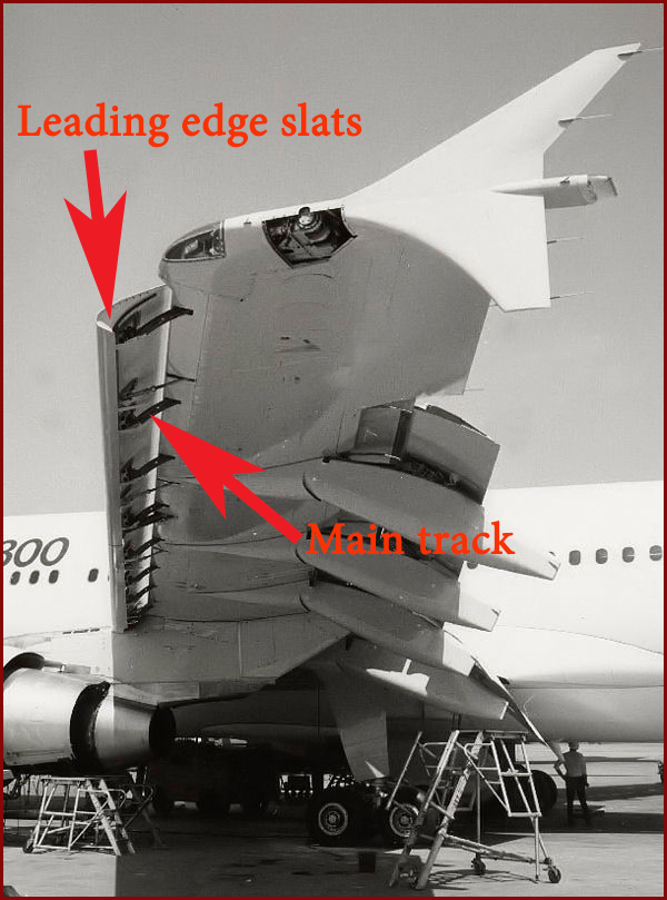
Leading edge slats prevent the stall up to approximately 30 degrees incidence (angle of attack) by picking up a lot of air from below, where the slot is large (Figure 1.), accelerating the air in the funnel shaped slot (venturi effect) and blowing this fast air tangentially on the upper wing surface through the much smaller slot. This "pulls" the air around the leading edge, thus preventing the stall up to a much higher angle of incidence and lift coefficient. The disadvantage of the leading edge slat is that the air accelerated in the slot requires energy which means higher drag. As the high lift is needed only when flying slowly (take-off, initial climb, and final approach and landing) the temptation for the designer is to use a retractable device which closes at higher speeds to reduce drag.
Figure 1.
This can be done in different ways: The slats can be mounted on roller rails so that at high angles of attack they are automatically pulled out by the airstream around the leading edge, and in cruise (at lower angle of attack) they are pushed in. This is a relatively simple system and not too heavy to design, but it has one big disadvantage: in gusty weather only one wing slat may be drawn out while the other stays in, creating a potentially major problem for the pilot who now needs full aileron just to keep the airplane level…!
So the safe way is to connect the right and left wing slats mechanically to prevent asymmetric extension. However, creating such an installation is heavy and more complex. The efficiency gained by the system must be very significant to compensate for the extra weight of the device (not to mention cost and complexity). A pilot controlled slat extension system is another approach, but has the same drawbacks: weight and complexity.
Modern slats are typically electrically or hydraulically powered and controlled automatically by a flight computer or by pilot commands.
Figure 2,
But there is a simple solution: The amount of drag increase created by the slot depends on the amount of air going through the slot in the whole range of flight. In take-off and landing configurations we want maximum lift, and in cruise we want minimum drag. By equalizing the amount of air pressure on the top and bottom of the wing at the leading edge (where the slat is located) in cruise configuration, there is no air flowing through the slot, and thus no lost energy (or extra drag created). Equalizing air pressure is easily achieved in cruise configuration with a slight trailing edge upward deflection of the wing flap. Figure 2. illustrates the lift coefficient and drag of such a wing design.
The illustration clearly shows that the wing with slats and flaps is the solution for slow flight where high lift is required, and also has little drag penalty in cruise. It is a light weight wing with no moving mechanical parts associated with the leading edge slats. A noticeable drawback is a relatively small low drag range, which means a narrow economical cruise speed range, but the overall configuration provides the best wing design for a STOL aircraft.
The disadvantage of leading-edge slats is that the air acceleration in the slot requires energy (it creates additional drag). While many STOL designs utilize retractible leading-edge slat devices, the additional weight, complexity, reliability issues and cost of such systems minimize their feasibility for use in light aircraft and their overall effectiveness.
In today's airplanes of two varieties spread, one of the "Slat track concept", which the guides mentioned above shall be reimbursed by the slats (Boeing 737, Airbus A320) and the other a "Droop Nose Device" (Airbus A380), in which joint mechanisms to move the slats. Advantages of the "droop nose device" are at the same lift, less the resistance than the "slat track" version, but the disadvantage is that it generates maximum lifting force is smaller.
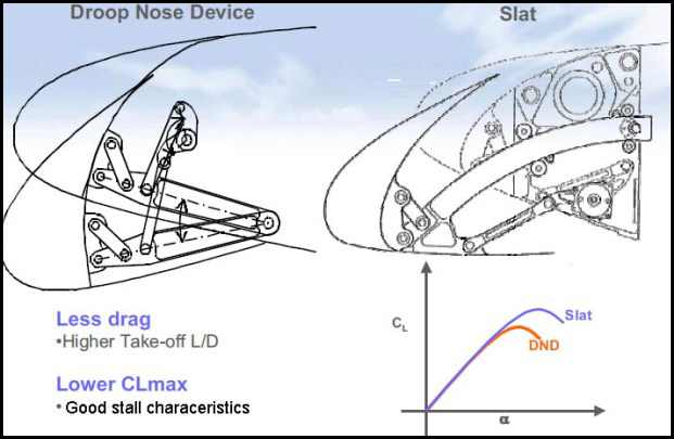
Landing Gear:
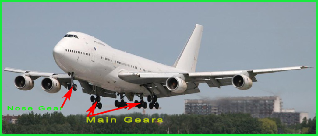
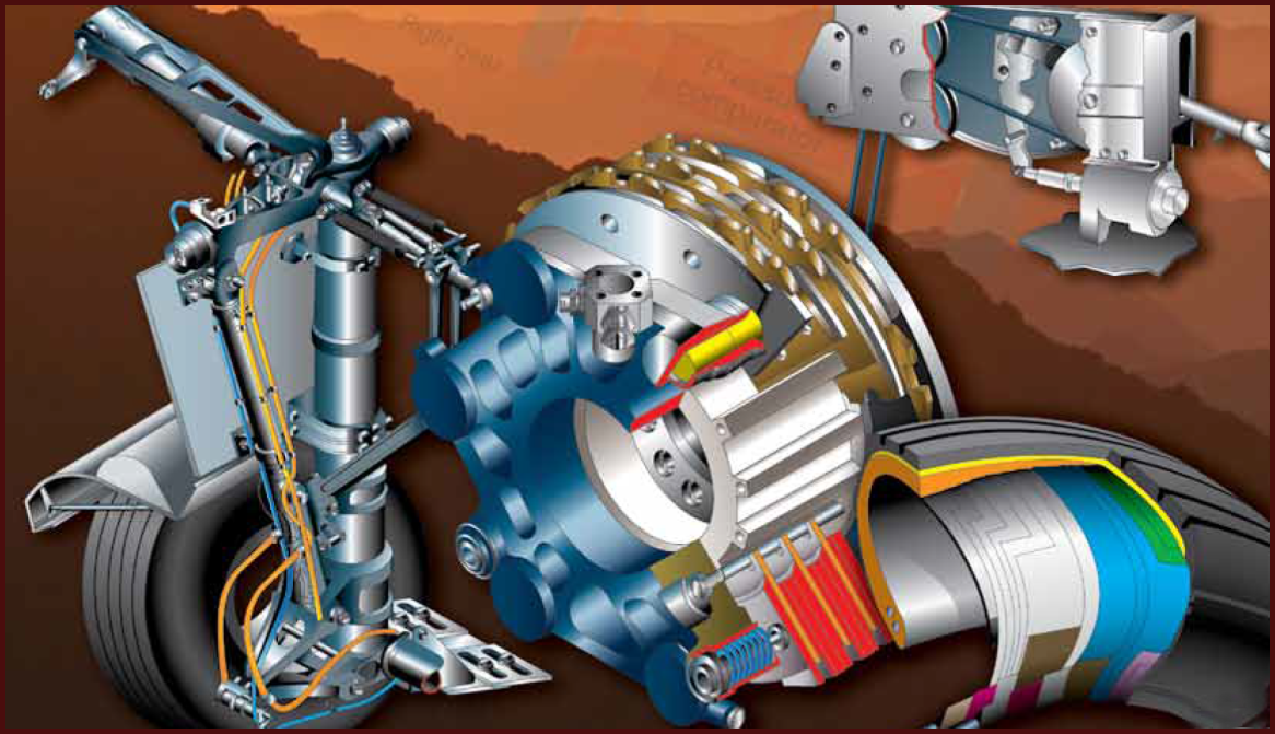
Aircraft landing gear supports the entire weight of an aircraft during landing and ground operations. They are attached to primary structural members of the aircraft. The type of gear depends on the aircraft design and its intended use. Most landing gear have wheels to facilitate operation to and from hard surfaces, such as airport runways. Other gear feature skids for this purpose, such as those found on helicopters, balloon gondolas, and in the tail area of some tail dragger aircraft. Aircraft that operate to and from frozen lakes and snowy areas may be equipped with landing gear that have skis. Aircraft that operate to and from the surface of water have pontoon-type landing gear. Regardless of the type of landing gear utilized, shock absorbing equipment, brakes, retraction mechanisms, controls, warning devices, cowling, fairings, and structural members necessary to attach the gear to the aircraft are considered parts of the landing gear system.
Three basic arrangements of landing gear are used: tail wheeltype landing gear (also known as conventional gear), tandem landing gear, and tricycle-type landing gear:
- Tail wheel-type landing gear is also known as conventional gear because many early aircraft use this type of arrangement. The main gear are located forward of the center of gravity, causing the tail to require support from a third wheel assembly. A few early aircraft designs use a skid rather than a tail wheel.
- Few aircraft are designed with tandem landing gear. As the name implies, this type of landing gear has the main gear and tail gear aligned on the longitudinal axis of the aircraft. A few military bombers, such as the B-47 and the B-52, have tandem gear, as does the U2 spy plane. The VTOL Harrier has tandem gear but uses small outrigger gear under the wings for support. Generally, placing the gear only under the fuselage facilitates the use of very flexible wings.
- The most commonly used landing gear arrangement is the tricycle-type landing gear. It is comprised of main gear and nose gear. Tricycle-type landing gear is used on large and small aircraft with the following benefits: 1. Allows more forceful application of the brakes without nosing over when braking, which enables higher landing speeds. 2. Provides better visibility from the flight deck, especially during landing and ground maneuvering. 3. Prevents ground-looping of the aircraft. Since the aircraft center of gravity is forward of the main gear, forces acting on the center of gravity tend to keep the aircraft moving forward rather than looping, such as with a tail wheel-type landing gear.
On light aircraft, the nose gear is directed through mechanical linkage to the rudder pedals. Heavy aircraft typically utilize hydraulic power to steer the nose gear. Control is achieved through an independent tiller in the flight deck. The main gear on a tricycle-type landing gear arrangement is attached to reinforced wing structure or fuselage structure. The number and location of wheels on the main gear vary. Many main gear have two or more wheels (Figure 1).
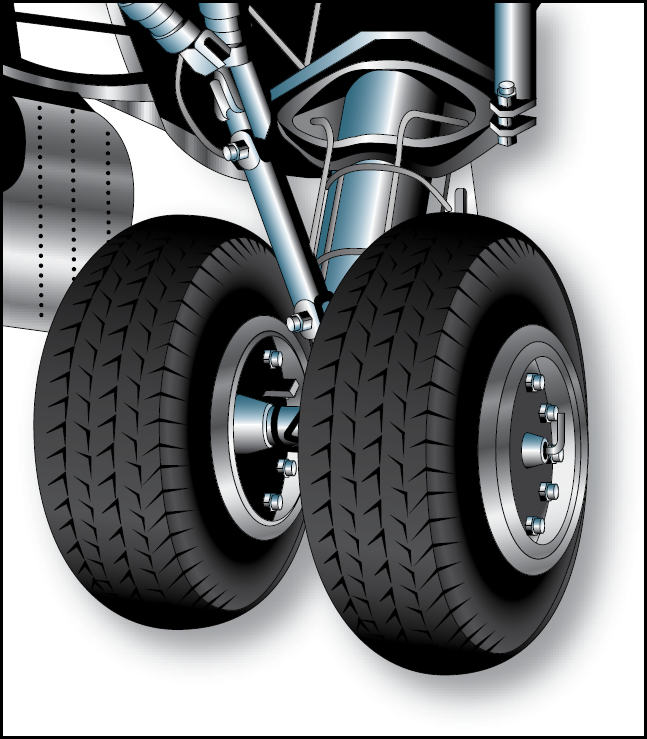
Figure 1. Dual main gear of a tricycle-type landing gear.
Heavy aircraft may use four or more wheel assemblies on each main gear. When more than two wheels are attached to a landing gear strut, the attaching mechanism is known as a bogie. The number of wheels included in the bogie is a function of the gross design weight of the aircraft and the surface type on which the loaded aircraft is required to land (Figure 2).
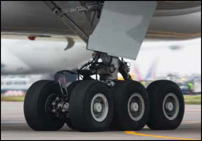
Figure 2. The triple bogie main gear of a Boeing 777.
The tricycle-type landing gear arrangement consists of many parts and assemblies. These include air/oil shock struts, gear alignment units, support units, retraction and safety devices, steering systems, wheel and brake assemblies, etc. A main landing gear of a transport category aircraft is illustrated in Figure 3, with many of the parts identified as an introduction to landing gear nomenclature.
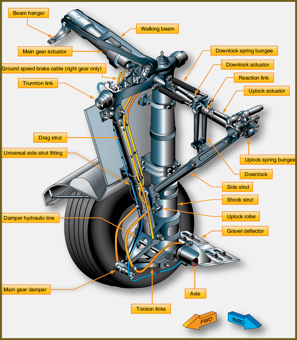
Figure 3. Nomenclature of a main landing gear bogie truck.
Further classification of aircraft landing gear can be made into two categories: fixed and retractable. Many small, singleengine light aircraft have fixed landing gear, as do a few light twins. This means the gear is attached to the airframe and remains exposed to the slipstream as the aircraft is flown. As the speed of an aircraft increases, so does parasite drag. Mechanisms to retract and stow the landing gear to eliminate parasite drag add weight to the aircraft. Retractable landing gear stow in fuselage or wing compartments while in flight. Once in these wheel wells, gear are out of the slipstream and do not cause parasite drag. Most retractable gear have a close fitting panel attached to them that fairs with the aircraft skin when the gear is fully retracted. The parasite drag caused by extended landing gear can be used by the pilot to slow the aircraft. The extension and retraction of most landing gear is usually accomplished with hydraulics.
Shock Absorbing and Non-Shock Absorbing Landing Gear: In addition to supporting the aircraft for taxi, the forces of impact on an aircraft during landing must be controlled by the landing gear. This is done in two ways: 1) the shock energy is altered and transferred throughout the airframe at a different rate and time than the single strong pulse of impact, and 2) the shock is absorbed by converting the energy into heat energy.
Shock strut
True shock absorption occurs when the shock energy of landing impact is converted into heat energy, as in a shock strut landing gear. This is the most common method of landing shock dissipation in aviation. It is used on aircraft of all sizes. Shock struts are self-contained hydraulic units that support an aircraft while on the ground and protect the structure during landing.
There are many different designs of shock struts, but most operate in a similar manner.
A typical pneumatic/hydraulic shock strut uses compressed air or nitrogen combined with hydraulic fluid to absorb and dissipate shock loads. It is sometimes referred to as an air/oil or oleo strut. A shock strut is constructed of two telescoping cylinders or tubes that are closed on the external ends. The upper cylinder is fixed to the aircraft and does not move. The lower cylinder is called the piston and is free to slide in and out of the upper cylinder. Two chambers are formed. The lower chamber is always filled with hydraulic fluid and the upper chamber is filled with compressed air or nitrogen. An orifice located between the two cylinders provides a passage for the fluid from the bottom chamber to enter the top cylinder chamber when the strut is compressed. [Figure 4]

chamber during compression.
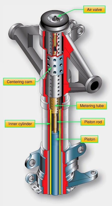
metering tube rather than a metering pin to control the flow of fluid
from the bottom cylinder to the top cylinder.
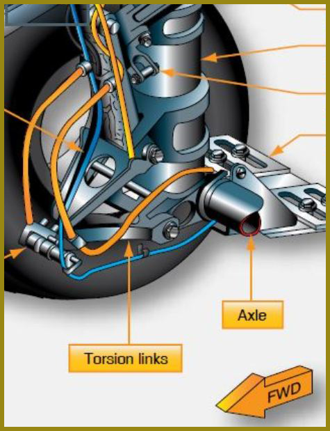
piston in the upper cylinder when the strut is extended.
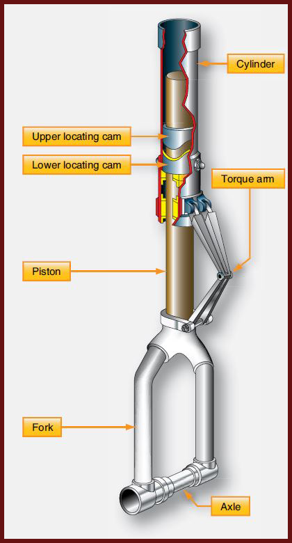
when the nose landing gear shock strut is extended before landing
and before the gear is retracted into the wheel well.

for attaching a tow bar.
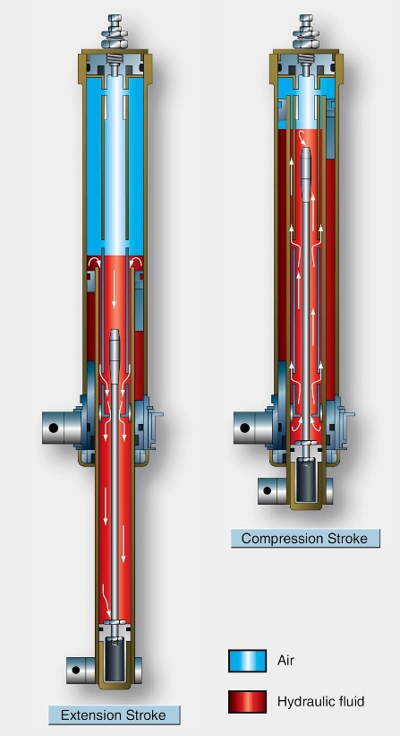
by the taper of the metering pin in the shock strut orifice.
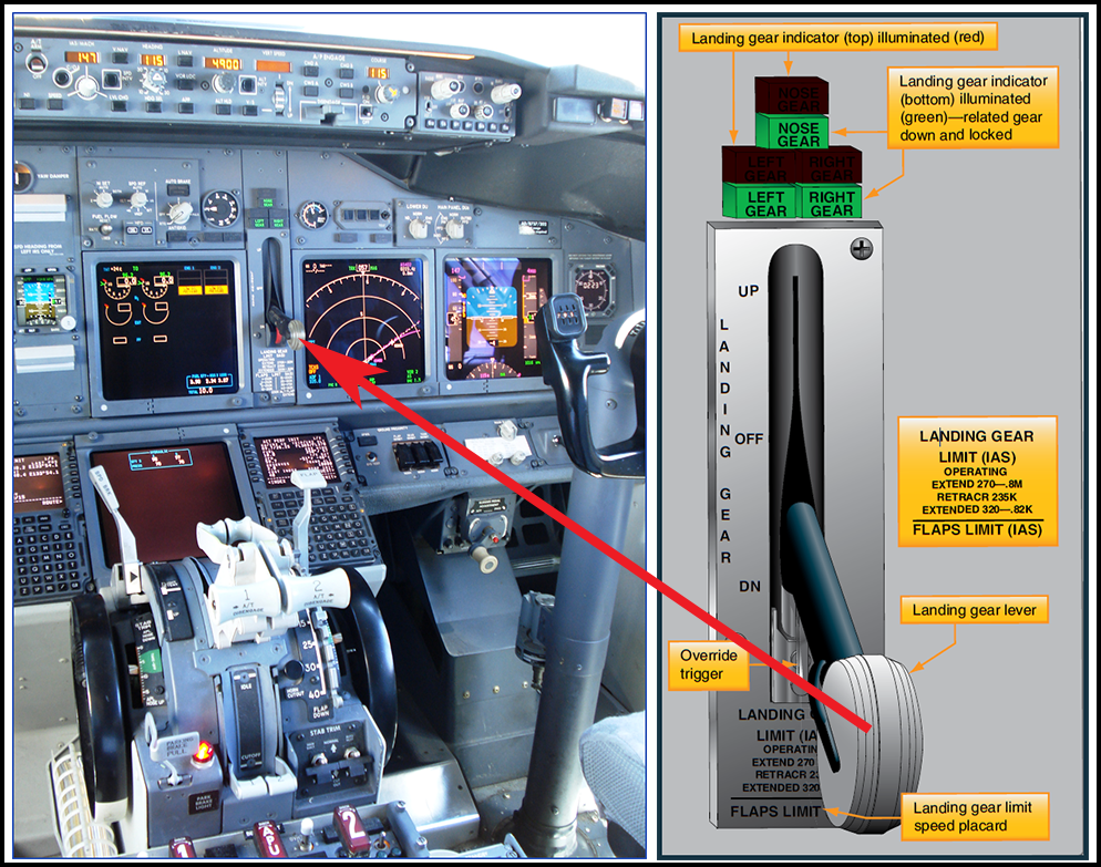
Landing gear position indicators are located on the instrument panel adjacent to the gear selector handle. They are used to inform the pilot of gear position status. There are many arrangements for gear indication. Usually, there is a dedicated light for each gear. The most common display for the landing gear being down and locked is an illuminated green light. Three green lights means it is safe to land. All lights out typically indicates that the gear is up and locked, or there may be gear up indicator lights. Gear in transit lights are used on some aircraft as are barber pole displays when a gear is not up or down and locked. Blinking indicator lights also indicate gear in transit. Some manufacturer’s use a gear disagree annunciation when the landing gear is not in the same position as the selector. Many aircraft monitor gear door position in addition to the gear itself [Figure 10].
such as pneumatic power, to unlatch the gear [Figure 11] .

unit. The control unit is a hydraulic metering or control valve. It directs hydraulic fluid under pressure to one or two actuators designed with various linkages to rotate the lower strut. An accumulator and relief valve, or similar pressurizing assembly, keeps fluid in the actuators and system under pressure at all times. This permits the steering actuating cylinders to also act as shimmy dampers. A follow-up mechanism consists of various gears, cables, rods, drums, and/or bell-crank, etc. It returns the metering valve to a neutral position once the steering angle has been reached. Many systems incorporate an input subsystem from the rudder pedals for small degrees of turns made while directing the aircraft at high speed during takeoff and landing. Safety valves are typical in all systems to relieve pressure during hydraulic failure so the nose wheel can swivel [Figure 12].

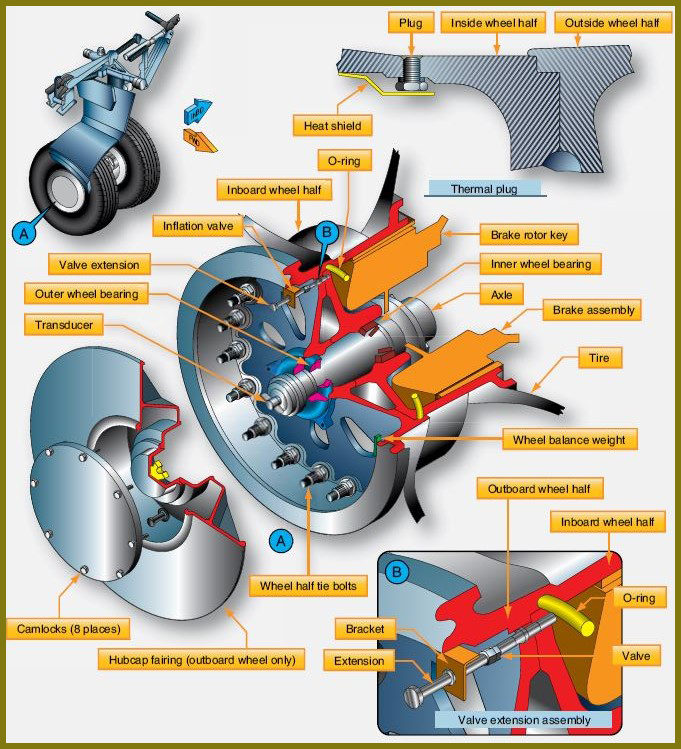
common types of brakes. Segmented rotor brakes are used on large aircraft. Expander tube brakes are found on older large aircraft. The use of carbon discs is increasing in the modern aviation fleet.


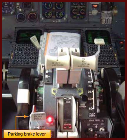
pedestal throttle quadrant.
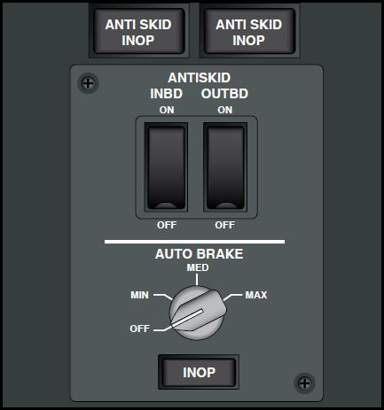
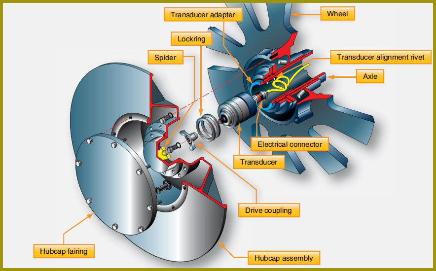
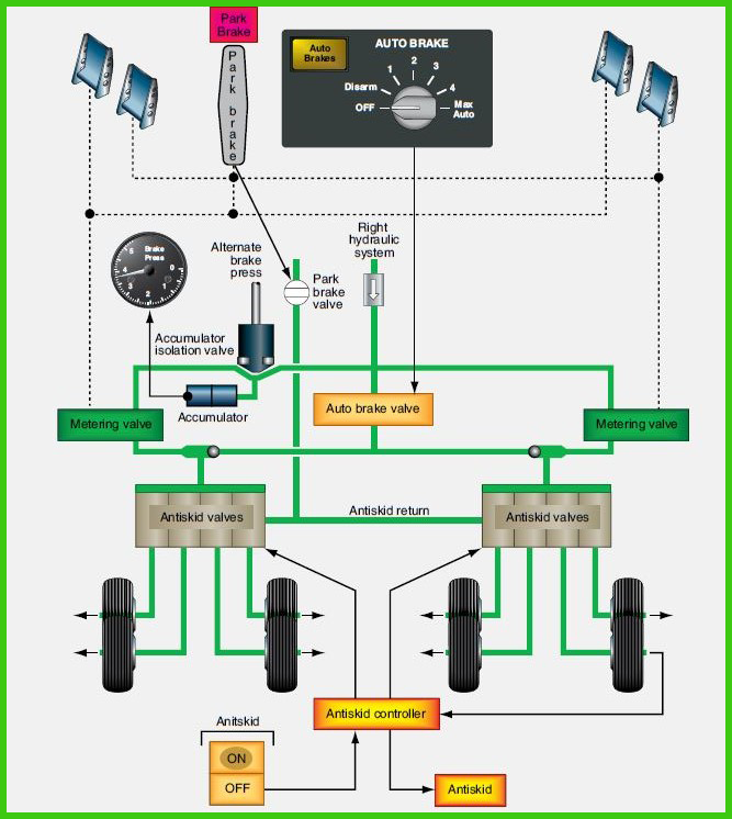
anti-skid system. This allows the brakes to be applied as retraction occurs so that no wheel rotation exists while the gear is stowed.
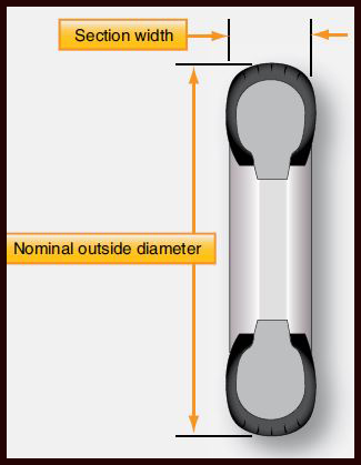

bias or radial. Traditional aircraft tires are bias ply tires. The plies are wrapped to form the tire and give it strength. The angle of the plies in relation to the direction of rotation of the tire varies between 30° and 60°. In this manner, the plies have the bias of the fabric from which they are constructed facing the direction of rotation and across the tire. Hence, they are called bias tires. The result is flexibility as the sidewall can flex with the fabric plies laid on the bias. [Figure 22].