A - B
Introduction to the Aviation A-Z Guide
Today many people travel by plane. It doesn’t matter whether you are technical minded or not, but when you take your seat on board the aircraft you should remember that your journey is due to enormous technical achievements. Furthermore, your airplane can take you to almost every point on the planet.
My A-Z aviation guide will help you understand the technology of flight and I will be adding to it on a regular basis. I welcome any comments and thank you in advance.
I wish you a pleasant flight and hope that you enjoy browsing:
ACARS ( Aircraft Communications Addressing and Reporting System ):
In civil aviation, air data system, the early days between the pilots and the ground of the VHF or HF radio communication system. The ACARS system is the introduction of the first attempts in the US ARINC (Aeronautical Radio, Incorporated) company carried out the communications equipment industry, even in 1978.
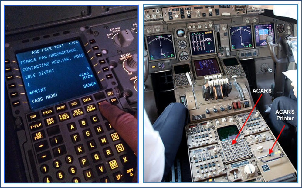
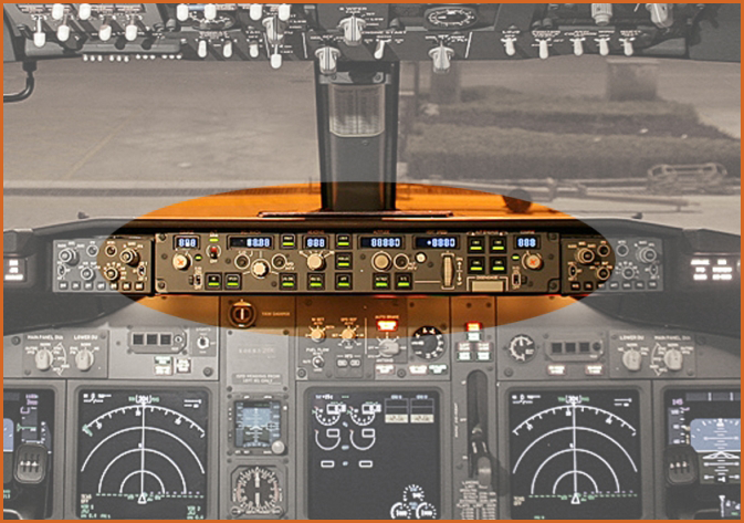
The commonly used today for data communication system ACARS (Aircraft Communications Addressing and Reporting System) over open waters and uninhabited areas via satellite (Satcom) work. Upon request, sending a variety of auto flight and technical reports to the operator, service to service, but less able to transmit navigation and text messages. A communication system, which focuses on the maintenance and operation of the plans help. The relationship between the airline and the aircraft provides. Since the 90's satellite system typically takes place the cross in data traffic. If a fault occurs on an airplane, you will be able to send messages to the ground, so the maintenance staff had knowledge of the problem and is ready and waiting for the machine to perform the repair. Pilots can communicate with the airline or so in the air without maintenance with radio. The figure is not an everyday "ACARS message," read the message when the crew "earth", "FEMALE PAX UNCONSCIOUS" an unconscious woman passenger on board.
The ACARS system is not a substitute for the black box, since its purpose is not, and is not suitable for this job. They will be developed in the communication, such as Internet-based communication, or some other system in the future, but until then performs a great service to the ACARS, around the world.
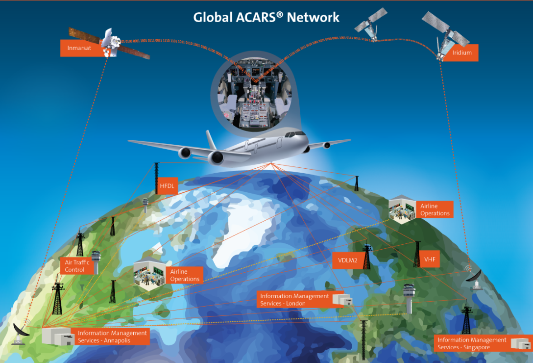
If a pilot needs a weather report to navigate a storm—at the touch of a button, and within seconds, Rockwell Collins’ ARINC ACARS® sends timely, accurate information that crew members can display or print. ACARS—the only data link infrastructure with pole-to-pole global coverage—delivers the critical reliability airlines depend on every day.
Thirty years ago, ACARS revolutionized air-to-ground communications, transitioning an entire industry from legacy, voice-reliant systems to data link. It quickly became the standard in aviation, and today is the most trusted, proven, and reliable—achieving 99.999% availability—communications system in the world.
Designed to reduce workload and improve data integrity, ACARS is a beacon of operational efficiency for airlines—perpetuating critical, automated, real-time messaging between the flight crew and air traffic control (ATC).
ACARS is also optimized for each airline’s unique needs—featuring custom applications, hardware requirements, formatting and language, and scalable control displays. With such versatility, ACARS performs many crucial functions:
- Abnormal flight condition identification
- Detailed engine reports
- Repair and maintenance plan
- Manual email-type messaging between crew and ATC
- Weather reports
ACARS benefits airline communications across the board. Our highly reliable, world-wide data link coverage still remains the aviation communications standard.
Active Gust Alleviation:
The commercial airplanes is a common problem for passengers in air turbulence (Air Pocket), when staff turns on the "fasten seat belts" tableaux, and in this case they experience a certain discomfort of passengers. In today's modern aicrafts are now flying at high altitudes, above the weather fronts, but it is nevertheless often the case, the vertical air movement (Vertically active), and this phenomenon some passengers fear, or cause nausea.
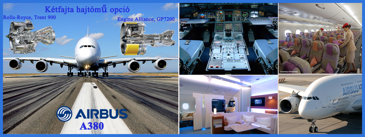
The Boeing Dreamliner aircraft of the latest known Boeing 787 ( and Airbus A380 ) thinking about this problem, and boost wind-mitigation system designed to alleviate the unpleasant feelings, fears.
A gust alleviation system is a control system fitted to some Fly-by-wire (FBW) aircraft that reduces the effect of gust loads on the aircraft by deflecting control surfaces such as ailerons, rudder and elevators.
The system works by measuring the upward acceleration of the aircraft and comparing that with the acceleration commanded by the (auto)pilot. A feedback loop adds a correction signal to the signals controlling the deflection of the control surfaces in order to counteract the accelerations cause by wind gusts.
In its simplest form the accelerations are sensed near the center of gravity of the aircraft. More advanced implementations work with multiple sensors in the body and in the wings. These gust alleviation systems do not only attempt to annul the effect of the gusts on the aircraft's normal (upward) acceleration, they also reduce the wing bending moments. This is turn reduces metal fatigue.
In the A380 the load alleviation system is nicknamed "valse des aileron" (Waltz of the Ailerons) because of the dancing movements of the aileron:
Gusts change the dynamic pressure of the airflow over the wing. Vertical gusts even change the angle of attack. Both will change the lift the wing creates, and especially vertical gusts add stresses for the structure and discomfort for the passengers.
By changing aileron deflection, the wing's lift can also be manipulated. If the aileron deflection is just enough to compensate the added aerodynamic load due to a gust, both the wing and the passengers will benefit. By coupling the readings of accelerometrs near the wing tip, the FCS can adjust the aileron deflection and ideally keep the wing bending constant.
Since the ailerons are at the outer 30% of span, they have a big influence on the root bending moment, but affect only a small part of the lift the wing can create. Therefore, while the bending moment can be nicely held constant, the lift will still vary, but less than without gust alleviation.
The part referring to the stick in the quoted patent refers to a mechanical control system with a naturally stable aircraft. If an aircraft with such a control system flies into a vertical gust, it will pitch up or down, which in turn will shift the equilibrium stick position. However, this will happen with some delay (the fuselage tip will "see" the gust first, and the tail will be affected by it some tenths of a second later), so the stick movement is a poor source for a feedback loop. I wonder why the patent mentions it - maybe the patentee wanted to cover all input sources.
AIRBUS COMPANY:
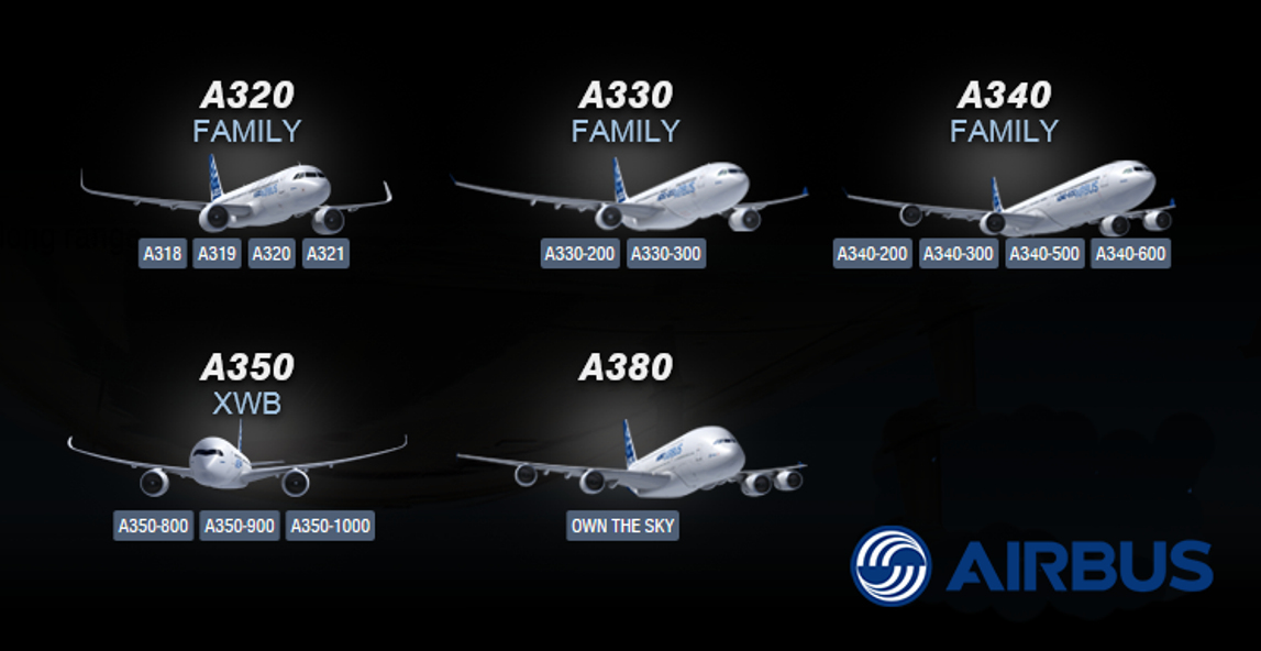
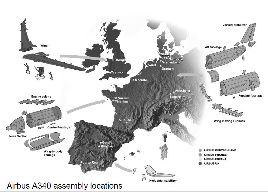
Airbus Industrie began his career in European factories aircraft (Hawker Siddeley, Aérospatiale, Deutsche Airbus, Fokker VFW, CASA) in 1970 as a consortium. Airbus is Boeing and McDonnell Douglas company was set up to reduce the huge market share, and in 1960 the consortium was large enough that they competes with your opponents. The Airbus S.A.S. aircraft manufacturer based in Toulouse, France, and the company under French law and a simplified joint stock company "SAS" (Société par Actions simplifiée - Simplified Joint Stock Company). The Airbus formerly known as Airbus Industrie, nowadays simply Airbus is sometimes called. According to 2015 data employs 57 thousand employees, three European countries (England, Germany and Spain) together. Production in Toulouse and Hamburg is going on. The first aircraft of the Airbus A300 as it was that retired from the world's first two-engined, two-passenger corridor airliner in the history of aviation. A shortened version of the A300's, A310's in 1982, took off for the first time. Because these aircraft fail, chose the Airbus A320 in addition to the construction of which was used the first fly-by-wire control system, and in fact is one of the most successful Airbus series has become. The year 2005 saw the world's largest passenger aircraft Airbus in the production of the A380, and further afield, according to 2015 data from the beginning of the year has 150 pieces were produced down. Seeing this type can be proud of.
Air control :
The Air Controller is in charge of the movements on the runways as well as for the air traffic in the vicinity of the airport. He clears aircraft for take-off or landing, thereby ensuring that the assigned runway is clear for the foreseen manoeuvre. Regarding the traffic in the air, the air controller is responsible for managing a controlled airspace called “CTR” that covers the airport and in which he ensures the safety of the approaching or departing aircraft by giving adequate instructions. If the air controller detects potentially unsafe conditions, he can tell the pilot of an aircraft in landing phase to go around or even order an aircraft to abort departure.
At the tower, a highly disciplined communication and collaboration process between air and ground controllers is an absolute necessity. But the co-ordination with other air traffic controllers does not stop there: it is also advisable to co-ordinate with the radar controllers the distances separating approaching aircraft in view of creating the necessary distance for aircraft taking off or for crossing the runway.
Aircraft deicing:
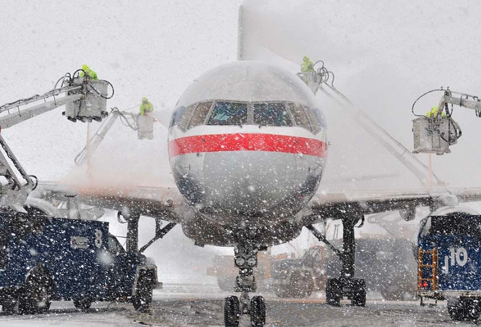
If somebody have traveled by air in wintry weather, They've probably looked out the window before takeoff and seen vehicles circling the plane, spraying deicing fluid on the wings. Passengers often ask the stafs why it's so important to make sure the aircraft is free of snow and ice accumulation.
Not just removing, but also preventing a build-up of snow and ice on the wings and tail of an airplane is crucial for a safe take-off. A plane's wings and rear tail component are engineered with a very specific shape in order to provide proper lift for flight. Snow and ice on these areas in essence changes their shape and disrupts the airflow across the surface, hindering the ability to create lift.
Whenever snow, ice, or even frost has accumulated on the aircraft, the pilots call on the airport deicing facility to have it removed. Deicing fluid, a mixture of a chemical called glycol and water, is generally heated and sprayed under pressure to remove ice and snow on the aircraft.
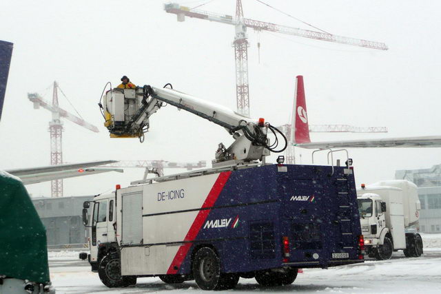
While it removes ice and snow, deicing fluid has a limited ability to prevent further ice from forming. If winter precipitation is falling, such as snow, freezing rain or sleet, further action needs to be taken to prevent ice from forming again on the aircraft before takeoff.
In these cases, anti-icing fluid is applied after the deicing process is complete. This fluid is of a higher concentration of glycol than deicing fluid. It has a freezing point well below 32 degrees Fahrenheit or zero Celsius and therefore is able to prevent the precipitation that falls into it from freezing on the plane's surface.
Anti-icing fluid also has an additive that thickens it more than deicing fluid to help it adhere to aircraft surfaces as it speeds down the runway during takeoff.
Pilots temporarily disable the aircraft's ventilation system during the deicing/anti-icing process to prevent fluid fumes from entering the cabin. Although the fumes are considered nontoxic for inhalation, the staf try to keep the odor out of the cabin regardless. Sometimes the scent, similar to maple syrup, does find its way into the aircraft cabin.
As the anti-icing fluids lose their effectiveness in flight, the aircraft is still equipped with systems that prevent frozen precipitation from building on the wings, tail and various sensors around the airplane. These systems are not only important in the winter months, but also in the summer months, because at higher altitudes, the temperature is well below freezing year-round.
Typically aircraft systems prevent ice buildup in one of two ways. On most jet aircraft, hot air from the engines is routed through piping in the wings, tail and engine openings to heat their surfaces and prevent icing.
Preventing ice formation in the engine openings is important, as ice here could dislodge and cause damage as it's ingested into the engine. This occurrence would be similar to throwing a rock into a running washing machine -- clearly not a good idea.
On propeller driven aircraft, balloon-like devices attached to the wings and tail are inflated and deflated with air from the engines, breaking up any ice accumulation.
Aircraft marshalling:
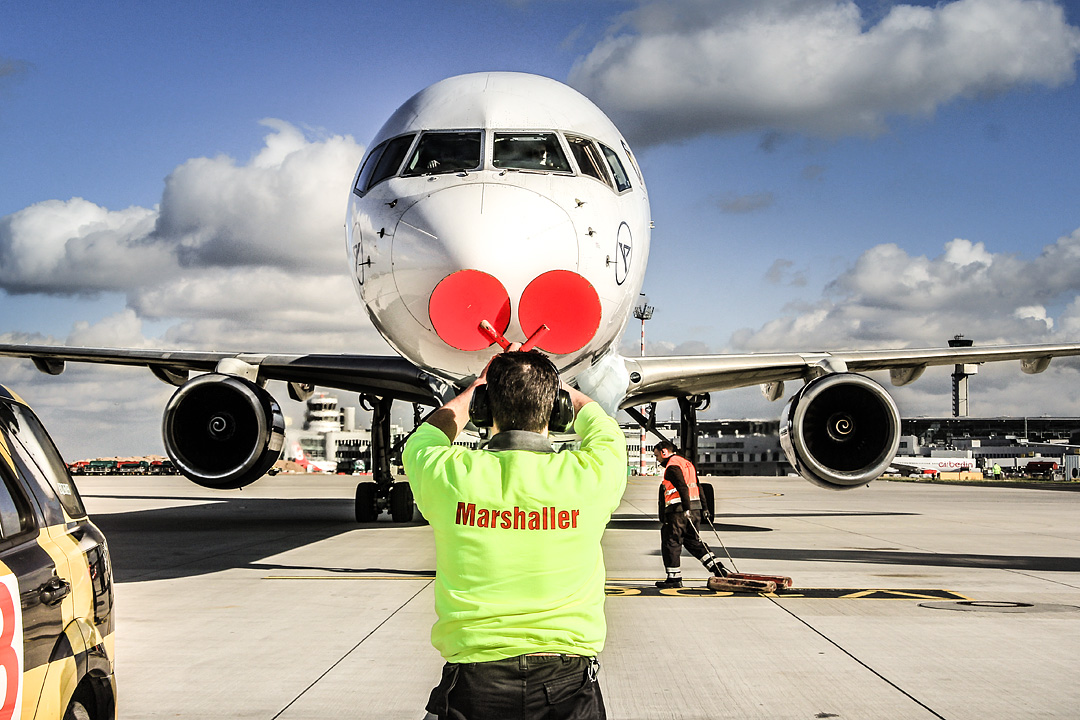
Aircraft marshalling referst to the visual communication between ground personnel and pilots in order to lead an aircraft to the correct parking position at an airport or aerodrome. Marshalling is important because many pilots have limited vision both of the aircraft and of ground obstacles from the cockpit. The marshaller, thus, guides the pilot to the parking position in a safe manner. Marshalling is also used for preparing the aircraft for departure as well. Aircraft marshalling is mainly done using visual communication through body signals.
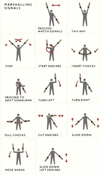
Marshalling "body signals"
Altitude measurement:
There is a lot of confusion for peeps as to what QNH, QFE, QNE and QFF settings all mean. Not sure if it's been explained before but I'll just do a quick info filler post for those new to altimeter pressure functions. Its a lot of info to take in but hopefully will ease the pain and I will summarise at the end.
History -These 'Q codes' originate from days way back when. Voice radio was hard to make out clearly at times, especially on HF frequencies. The reversion back to using morse code was then required to establish a clear method of communication. These Q codes were a set of 3 letters beginning with a Q. They were set up to transmit a sentence quickly with just morsing 3 letters. The Q originally was to signify a question. QRB = What is your distance. QRC = what is your true bearing etc.
As the codes developed they also incorporated statements such as QFE = Pressure at particular observation station (an airfield/port/oil rig/etc).
Just out of interest, Q codes reserved for aviation use are QAA–QNZ. There are reserved sets of codes for maritime and sets used by all services.
Q codes we use on a day to day basis in aviation relate to headings too, QDM, QDR, QTE, QFU and QUJ. They all have a standard meaning attached to them and allowed the old morse operators to transmit info far more quickly. I wont go into these in this thread... maybe another future thread if there is enough interest
So, history lesson out the way... what do the pressure setting Q codes actually mean?
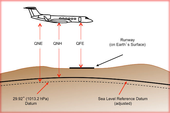
QNH = The pressure measured at station then reduced down to mean sea level pressure. When set on your altimeter it will read your ALTITUDE. Sat on the tarmac at your airfield the altimeter will display the airfields elevation above mean sea level.
This is the most commonly used pressure setting in the commercial world. Its probably the most useful setting to have, as nearly all aviation references to elevation are in relation to mean sea level. The mountain peaks on a map, airfield elevation, target elevation, minimum safe altitudes enroute etc. Incidently, QNH is given as a regional pressure setting and should be updated with new ones if you leave its area of reference into a new QNH pressure region. The QNH is the LOWEST FORECAST pressure at mean sea level for a given day to ensure that safe terrain seperation is maintained regardless of the days variation in pressure.
QFE = Is mean sea level pressure corrected for temperature, adjusted for a specific site or datum like an airfield, being the most obvious example. When this is set on your altimeter, it will read your HEIGHT not altitude. It will read zero at airfield elevation and after take off will read your HEIGHT above that specific airfield. If you fly to another airfield of different elevation and/or different QFE pressure, you will have to ensure you reset that particular airfields QFE if you want your altimeter to read zero on touchdown.
QFE is very good for new pilots who are remaining in the circuit around an airfield and keeps things simple for that task.
QFE Example: Airfield A with elevation 250ft above mean sea level. Airfield B elevation 300ft AMSL. A to B = 10miles. Assuming a uniform atmospheric pressure in the region.
Take off from A, altimeter reads 0ft on runway and after take-off reads HEIGHT above airfield A. Go and land at B and your altimeter will read 50ft on the runway. This is because B's HEIGHT is 50ft higher then A.
In this example, if we set the regional QNH, then the altimeter will read ALTITUDE and therefore the airfields altitude AMSL. Airfield A, altimeter will read 250ft. Airfield B will read 300ft. This is why QNH is the primary pressure setting used in aviation at lower levels. It is far simpler working in a setting that gives ALTITUDE, so you can reference your vertical position from everything on a map or chart. (All airfield plates (charts) have their altitudes AMSL on the plate.)
This is all good and well knowing that QNH is the best pressure setting to use in a region for vertical situational awareness. But it is not always possible to get the regional pressure setting QNH from accurate means and a reliable network of meteo stations. Remote airfields and isolated combat zones are just 2 examples where it'd be difficult to get an accurate QNH when you dont have access to good forecasts and numerous pressure sensing stations.
If pressure info isn't available then you can get QFE easily by selecting an altimeter setting that reads zero on the airfield. The number in the altimeter pressure window is your QFE.
To get QNH, you just need to know your elevation AMSL and set that in your altimeter. Airfield elevation = 250ft. Set altimeter to read 250ft. Pressure in the altimeter pressure window shows your QNH. (You have to remember that this wont be the lowest forecast QNH pressure for the day and just be cautious at low level. But thats why a radio altimeter is handy!)
QNE = the Internation Standard Atmosphere (ISA). It is the average mean sea level pressure around the globe. It is planet earths mean atmospheric pressure at sea level basically. This pressure setting is refered to as STANDARD in aviation. STANDARD is set from QNH when climbing up through the "Transition Level". Your altimeter will then read your FLIGHT LEVEL. A reading of 25,000ft is FL250. 5,000ft = FL050. 13,500ft = FL135
Aerodynamic drag:
We know that the vacuum left any self-gravity body are consistently increasing speed toward Earth, and the speed continues to increase without limit as long as some kind of obstacle does not conflict. The air velocity abandoned soon after the initial acceleration is constant, and this - the body vary in size - speed limit exceeded after any length of time or descent. Air forces created on the body which is moving in the air, or a standing by blow air . These air forces and could hamper the movement against the rate increase. . Whether the body is moving at a certain speed of the air resistance, the body is made up and the air flow around the body by the speed of equal and anticlockwise speed, the drag force will be the same size in both cases. This is the aerodynamics or the so-called reversibility principle of reversibility. The air resistance of the body mass of the property follows from the fact that rebels against any change that state of rest or uniform motion in a straight line from trying to throw me off my. If the body is moving in the air, then separated laterally directs the air particles and thus interfere with their dormancy. When it blew the air resistance body, the body also confuse the air particle velocity and direction. In both cases, the air exerts resistance, which occurs in the form of a pressure on the body.
The calculation of air resistance (X) used in the context of today as follows: X = cx x q x a
The aerodynamic formula for q = v² / 2, that is, the velocity squared / 2
The aerodynamic formula for "q" is so important to remember: the magnitude of the resistance in the case of a body varies with the square of the speed. "CX" in the formula is a dimensionless number, the resistance factor, the "A" (m2) is the body surface. For those bodies in the case where only the resistance forces arise, the formula for the body perpendicular to the direction of flow, the largest cross-sectional surface (front surface size) is substituted in. In the case of bodies in which the resistor is formed outside the flow direction is perpendicular to the force, in plan area of the body is selected from F and marking are used. Resistance factor in the formula is a number that refers to the body shape and quality. The easiest way of determining when we measure the X resistance force in the wind tunnel.
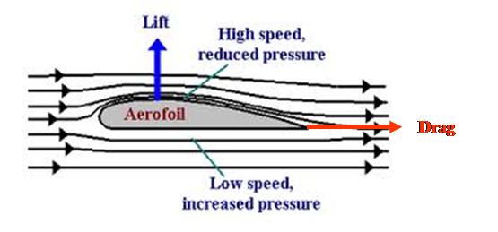
Aerofoil:
An aerofoil is the term used to describe the cross-sectional shape of an object that, when moved through a fluid such as air, creates an aerodynamic force. Aerofoils are employed on aircraft as wings to produce lift or as propeller blades to produce thrust. Both these forces are produce perpendicular to the air flow. Drag is a consequence of the production of lift/thrust and acts parallel to the airflow.
Other aerofoil surfaces includes tailplanes, fins, winglets, and helicopter rotor blades. Control surfaces (e.g. ailerons, elevators and rudders) are shaped to contribute to the overall aerofoil section of the wing or empennage
Several terms are used to describe aerofoils:
- Leading Edge = Forward edge of the aerofoil
- Trailing Edge = Aft edge of the aerofoil
- Chord = Line connecting the leading and trailing edge. Denotes the length of the aerofoil
- Mean Camber Line = Line drawn half way between the upper and lower surface of the aerofoil. Denotes the amount of curvature of the wing
- Point of Maximum Thickness = Thickest part of the wing expressed as a percentage of the chord
By altering each of the above features of an aerofoil, the designer is able to adjust the performance of the wing so that it is suitable for it's particular task. For example, a crop duster may have a thick, high camber wing that produces a large amount of lift at low speed. Alternatively, a jet would have a thin wing with minimal camber to allow it to cruise at high speeds.
The basic principle behind an aerofoil is described by bernoullis theorem. Basically this states that total pressure is equal to static pressure (due to the weight of air above) plus dynamic pressure (due to the motion of air).
Air that travels over the top surface of the aerofoil has to travel faster and thus gains dynamic pressure. The subsequent loss of static pressure creates a pressure difference between the upper and lower surfaces that is called lift and opposes the weight of an aircraft (or thrust that opposes drag).
As the angle of attack (the angle between the chord line and relative air flow) is increased, more lift is created. Once the critical angle of attack is reached (generally around 14 degrees) the aerofoil will stall.
Aft pressure bulkhead:
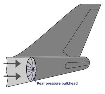
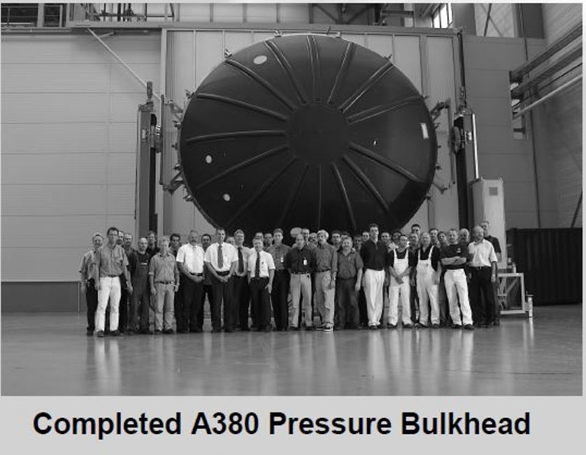
Airbus A 380 aft pressure bulkhead is made by composite material
The rear pressure bulkhead is probably one of the most important elements of a commercial aircraft. The bulkhead is located between the passenger cabin in the tail of the aircraft, the passenger can not see all of this, of course, because after a relatively complicated disrupting, dismantling operation is visible. Responsible for sealing the rear of the aircraft, thereby maintaining the pressure in the cabin that separates the pressurized fuselage and rear passenger compartment is not under pressure, is also highly stressed parts exposed and which becomes very significant unit of the aircraft. Generally oval shape, and an example of the size, Airbus A380, 5.5 x 6.2 m. Instead of metal partitions are now called for material CFRP (carbon fiber reinforced plastic) used particularly at Airbus, as this will achieve a significant weight reduction. The bulkhead has a very sad story unfortunately, when the Japan Airlines, number 123 flights with a Boeing 747 type aircraft in 1985 fell due to serious pressure drop and heavy hydraulic failure, where 509 passengers and 15 crew lost their lives due to the failure of repair by Boeing company ( They are used one rivet line, instead of two rivet lines).

Aileron:
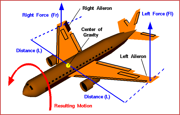
Ailerons can be used to generate a rolling motion for an aircraft. Ailerons are small hinged sections on the outboard portion of a wing. Ailerons usually work in opposition: as the right aileron is deflected upward, the left is deflected downward, and vice versa. This slide shows what happens when the pilot deflects the right aileron upwards and the left aileron downwards.
The ailerons are used to bank the aircraft; to cause one wing tip to move up and the other wing tip to move down. The banking creates an unbalanced side force component of the large wing lift force which causes the aircraft's flight path to curve. (Airplanes turn because of banking created by the ailerons, not because of a rudder input.
The ailerons work by changing the effective shape of the airfoil of the outer portion of the wing. As described on the shape effects slide, changing the angle of deflection at the rear of an airfoil will change the amount of lift generated by the foil. With greater downward deflection, the lift will increase in the upward direction. Notice on this slide that the aileron on the left wing, as viewed from the rear of the aircraft, is deflected down. The aileron on the right wing is deflected up. Therefore, the lift on the left wing is increased, while the lift on the right wing is decreased. For both wings, the lift force (Fr or Fl) of the wing section through the aileron is applied at the aerodynamic center of the section which is some distance (L) from the aircraft center of gravity. This creates a torque
T = F * L
about the center of gravity. If the forces (and distances) are equal there is no net torque on the aircraft. But if the forces are unequal, there is a net torque and the aircraft rotates about its center of gravity. For the conditions shown in the figure, the resulting motion will roll the aircraft to the right (clockwise) as viewed from the rear. If the pilot reverses the aileron deflections (right aileron down, left aileron up) the aircraft will roll in the opposite direction. We have chosen to name the left wing and right wing based on a view from the back of the aircraft towards the nose, because that is the direction in which the pilot is looking.
Air temperature, density and specific gravity:
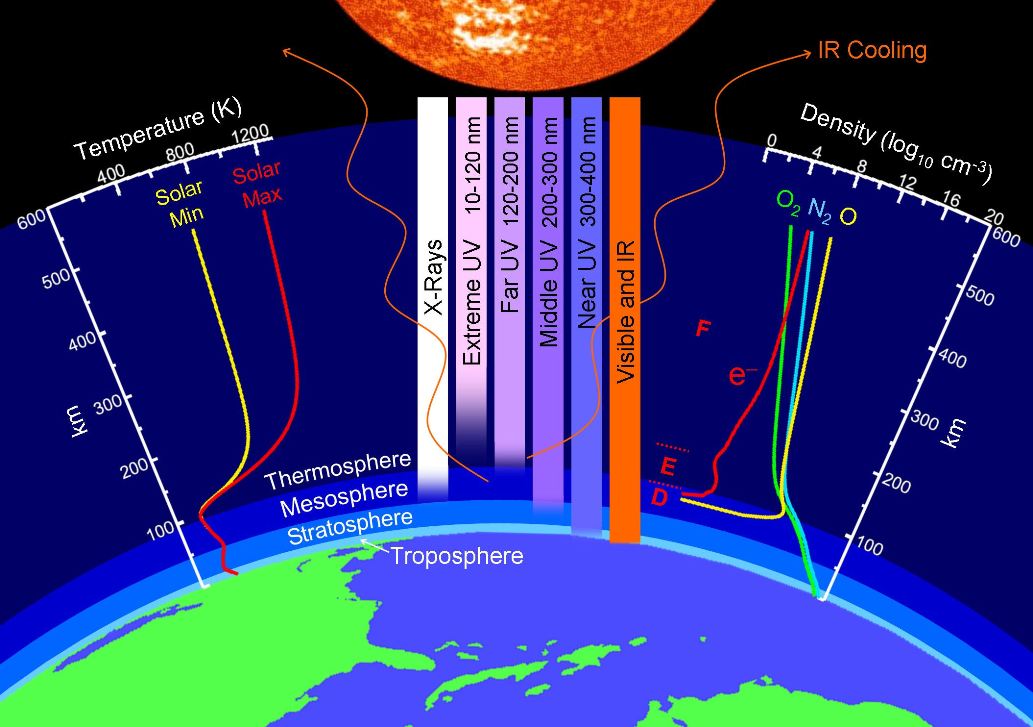
The air temperature decreases in the troposphere with height. 1 km change of altitude occurring during the temperature change is called temperature gradient. In the troposphere, the temperature gradient of 6.5 ° C / km.
The troposphere is the lowest layer of the atmosphere, extending from Earth’s surface to an altitude of about 11–13 km (7–8 mi). Above the troposphere lies the stratosphere, which extends from 13 km (8 mi) to about 44 km (27 mi). The temperature of the troposphere decreases steadily with increasing altitude. Because “hot air rises,” this temperature gradient leads to continuous mixing of the upper and lower regions within the layer. The thermally induced turbulence in the troposphere produces fluctuations in temperature and precipitation that we collectively refer to as “weather.” In contrast, mixing between the layers of the atmosphere occurs relatively slowly, so each layer has distinctive chemistry. We focus our attention on the stratosphere, which contains the highest concentration of ozone.
Above 11 km the air temperature t = -56.5 Cº ( 216.7 Kº ) and the temperature is constant about to 40 km in the stratosphere. Then again grow at a height of 55 km t = + 70 Cº up and cooling down after a new start at an altitude of 80 kilometers a second warming. The maximum value of the temperature over the Earth's upper reaches an altitude of 650 km, at t = + 2200Cº measured. The air temperature reduce again gradually more than 650 km altitude until the boundary of the atmosphere over the space, temperature reaches t = -273.2, ie the absolute zero degrees.
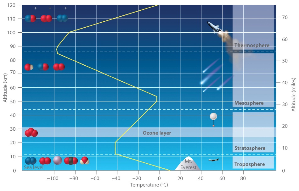
The yellow line indicates the temperature at various altitudes.
Temperature scales differ in two ways: the point chosen as zero degrees, and the magnitudes of incremental units or degrees on the scale.
The Celsius scale (°C) is used for common temperature measurements in most of the world. It is an empirical scale. It developed by a historical progress, which led to its zero point 0°C being defined by the freezing point of water, with additional degrees defined so that 100°C was the boiling point of water, both at sea-level atmospheric pressure. Because of the 100 degree interval, it is called a centigrade scale. Since the standardization of the kelvin in the International System of Units, it has subsequently been redefined in terms of the equivalent fixing points on the Kelvin scale, and so that a temperature increment of one degree Celsius is the same as an increment of one kelvin, though they differ by an additive offset of 273.15.
The United States commonly uses the Fahrenheit scale, on which water freezes at 32 °F and boils at 212 °F at sea-level atmospheric pressure.
Air density can be defined as the number of air molecules per unit volume (number density). Near sea level there are about 2.7x10¹⁹ molecules per cm3(cubic centimeter) or 4.4x10²⁰ molecules per inch3(cubic inch). Air molecules are held near the earth by gravity. In other words, air has weight. Weigh an empty bag, then fill it with air, it now weighs more. In addition gases, like air, are easily compressed, i.e., squeeze a gas together and its number density increases. In other words, we say gases are compressible because they can easily be squeezed into a smaller volume. Solids and liquids on the other hand are not easily compressed.
The weight of all of the air above a given point in the atmosphere squeezes air molecules closer together, which causes their numbers in a given volume to increase (increase in number density). The more air above a level (and hence the more weight of air above a level), the greater the squeezing effect (or compression).
Since air density is the number of air molecules in a given space (volume), air density is typically greatest at the surface or sea level (where it is squeezed by the weight of the entire atmosphere above) and decreases as we move up in the atmosphere because the weight of air above becomes less and hence there is less of a squeezing effect.
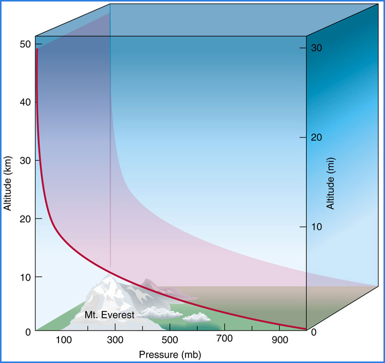
Typical change in air pressure with altitude. Note how rapidly air pressure falls with increasing altitude.
The term specific gravity, symbolized sp gr, refers to the ratio of the density of a solid or liquid to the density of water at 4 degrees Celsius. The term can also refer to the ratio of the density of a gas to the density of dry air at standard temperature and pressure, although this specification is less often used. Specific gravity is a dimensionless quantity; that is, it is not expressed in units.
To find the sp gr of a solid or liquid, you must know its density in kilograms per meter cubed (kg/m3) or in grams per centimeter cubed (g/cm3). Then, divide this density by the density of pure water in the same units. If you use kg/m3, divide by 1000. If you use g/cm3, divide by 1 (that is, leave the number alone). It is important to use the same units in the numerator and denominator.
Water has a specific gravity equal to 1. Materials with a specific gravity less than 1 are less dense than water, and will float on the pure liquid; substances with a specific gravity more than 1 are more dense than water, and will sink. An object with a density of 85 kg/m3 has a specific gravity of 0.085, and will float high on the surface of a body of water. An object with a density of 85 g/cm3 has a specific gravity of 85, and will sink rapidly.
To find the specific gravity of a gas, you must know its density in kilograms per meter cubed (kg/m3). Then, divide this density by the density of dry air at standard temperature and pressure. This value is approximately 1.29 kg/m3. Gases with a specific gravity less than 1 will rise in the atmosphere at sea level; gases with a specific gravity greater than 1 will sink and seek regions of low elevation at the earth's surface.
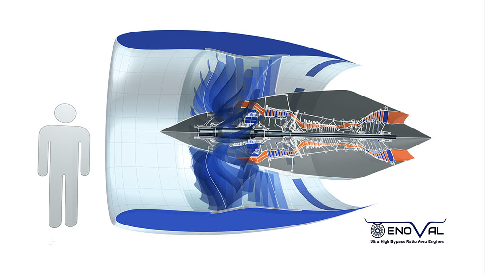
Aircraft engines:
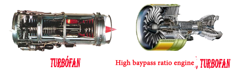
Today, different propulsion systems are being developed for the flight. Each aircraft engine types the usefulness M speed (Mach) range is shown below. The development is so rapid that the figure below shows the future is not the type of hyper-sonic propulsion engines, of which the reader of the website "Hobby / Aviation / Hyper Sonic engines", chapter you will find interesting information.
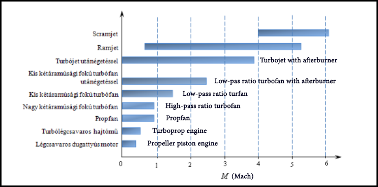
The dawn of the propeller-driven piston aviation engines to deliver the power needed for flight. Today, however, their use is expressly limited to lightweight, low-speed aircraft. Currently, more modern aircraft engine development projects seek to minimize the fuel consumption, the environmental impact and the price to be as low as possible. The propeller-driven piston engines is relatively low T / W , trust - weight, noisy and vibrating level is higher. Turbocharged engines can reaches the maximum altitude of approximately 7000 m.
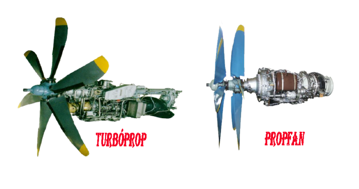
Turbo gear units (turboprop) power required for the compressor and the propeller rotate to ensure the gas turbine. The equivalent power (85-90)% - aa rotating propeller serve the remainder (15-10)% - was the reaction of the gearbox gives off gas jet. The turboprop engines advantages: higher T / W ratio, low speeds in the lower specific fuel consumption, and lower vibrating the higher the maximum flight level available to them. M (Mach) 0.5 in case of the turbofan engine propulsion efficiency is higher than the piston Moto, due to blast additional reactive thrust, however, the propeller driven aircraft flight Mach number is limited, because of the resulting end of the propeller wing shock waves. With its properties, the turboprop engines mainly spread in the heavy-duty medium-range aircraft. The improved version of the engine turboprop engine propfan. The propfan drive with greater speed flight can be achieved, usually around 0.8 M numeric value. The cruising speed, the engine propulsion efficiency propfan better specific fuel consumption is more favorable than a turboprop or high pass ratio turbofan.
The most effective engine is the turbofan engine at subsonic speeds. The transmissions of this class is an important feature of the by-pass degree, i.e. the high pressure air passing through the portion (primary current) and the air flowing through the low pressure area (secondary current) of the mass flow rate ratio. The by-pass is usually varies between 0 degrees and 6, but may be considerably higher. Pass ratio engines greater degree of relatively consume less, they are more environmentally friendly. The ratio of air-fuel at turbojets characteristic is greater than the ideal stoichiometric ratio. Large air surplus provides the external cooling of the turbine blades, the primary air approx. 25% is actually participating in the combustion process. In order to temporarily increase the thrust in the air rich combustion product, after the turbine, the additional fuel nozzle for injecting tube, burned again. This is the basic principle reheat. Afterburning increases the available thrust of more than 50%, but this substantially increases the fuel consumption and of course only some of the flight phase used when you need the extra thrust. TurboJet engines with afterburner were fitted at fighter aircraft. The afterburner is switched on for take-off only briefly, and apprehension in other combat activities.
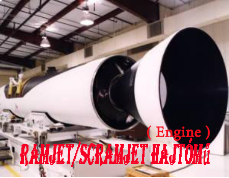
Ramjet, or in other words, without wiping jet rotary compressor, the air flow generated by an increase in pressure with slowdown required for operation. The ramjets is operatied above at certain speed, for the speed up is required other propulson . This type of engine is also available as M 6, M 4 but is considered the best. Scramjet is called ramjet with supersonic combustion chamber version. The air flow coming from at least M 4 added greatly increases the thrust of the engine. The scramjet is operating range of around Mach 4-6.
Aircraft engine starting:
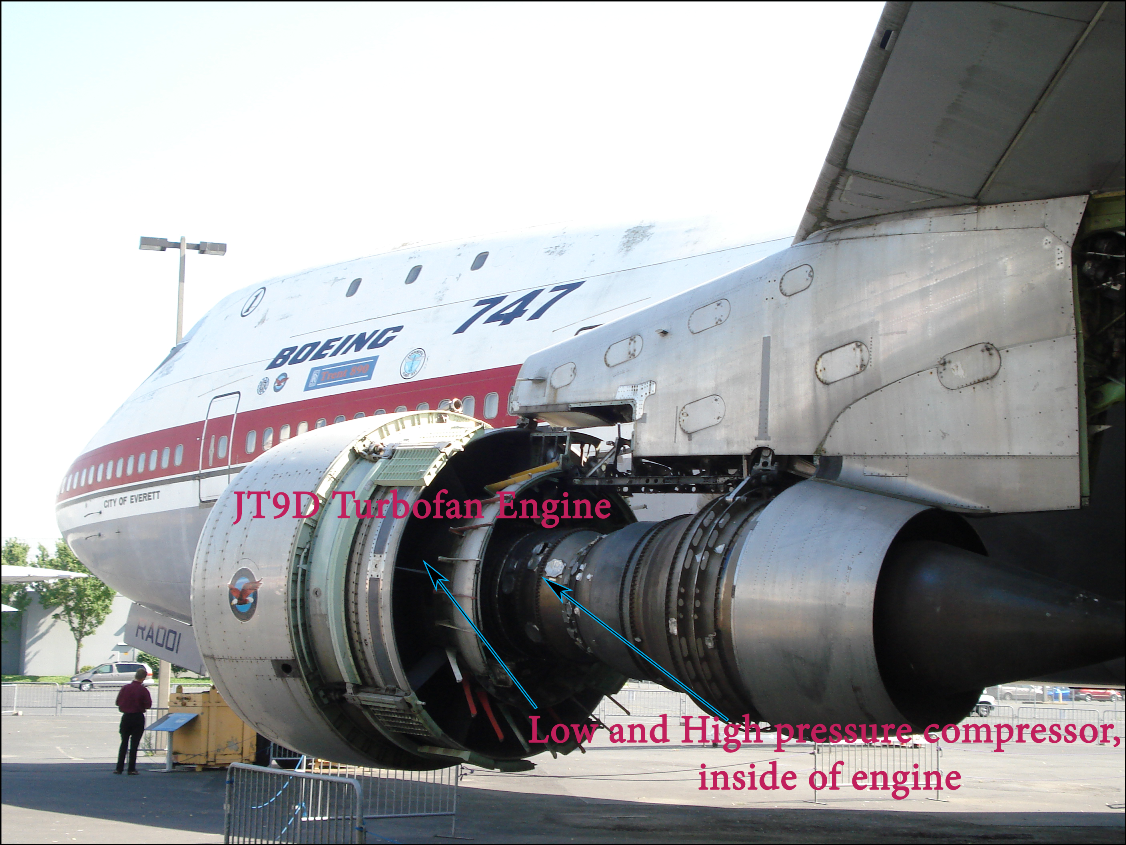
Predominant the civil aircrafts are equipped with gas turbine jet engines which engines themselves are unable to start (to spinning), because if the rotor is not rotating, there is no pressure before the turbine, and the turbine does not provide the work. Is enough to accelerate the engine, it is necessary to provide the the larger turbine work than the compressor work.
So when we take its our place on the airplane, at the startup, we hear a "strange" noise below the pushing process, as many times as engines provides the aircraft, well then initiated the pilots start the engines, and the "background" is a complicated as a result of complex process. After the completion of push back rotate the engines on idle position.
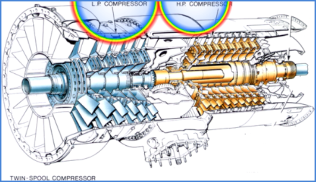
To understand all this, and that the start-up process is also clearly see, this is schematically understanding of the essential parts of a gas turbine jet engine rotating main units.
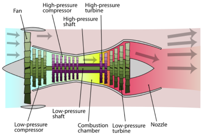
The N1 fan, N1 shaft and N1 turbine which are displayed in green and labelled "Fan/Low-pressure compressor", "Low pressure shaft" and "Low pressure turbine". These units are connected and move as one piece.
The N2 compressor, N2 shaft and N2 turbine, displayed in purple and labelled "High pressure compressor", "High Pressure shaft" and "High pressure turbine". These are connected and move as one, but independently of the N1 shaft. Un-pictured is an accessory drive that is geared to the N2 shaft to drive engine accessories.
The hot section, pictured yellow and labelled "Combustion chamber". This is home to a constantly burning fire in a jet engine.
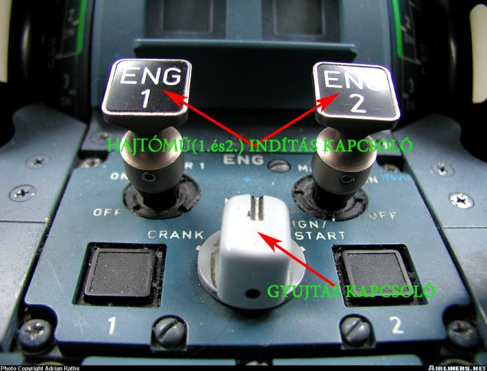
Starting a motor on an airbus is easy. Once cleared, we simply switch the Engine Ignition switch to “Start,” and flip the desired Engine Master switch up and On. The computer does the rest!
The process of the engine starting follows this basic formula:
-
Through the opening of bleed air valves, bleed air is sent to an air turbine starter. These devices typically use the high pressure bleed air to spin and engage a centrifugal clutch connected to the engines accessory drive. This in turn causes the N2 shaft within the engine to spin.
-
With the N2 shaft spinning, the N2 compressor and the N2 turbines are spinning. This begins to force air through the engine from front to back.
-
With the accessory shaft and N2 shafts spinning, accessories should start working and this can be verified by oil pressure indications on the EICAS.
-
With increased N2 rotation, ignition will be turned on. These igniters are located in the hot section of the engine and produce small sparks. There should be an indication on the EICAS that the ignition is active.
-
With further increase in N2 rotation, fuel flow will be introduced. This will be verified on the EICAS. Once fuel flow is noted, it is important that the next stop happen fairly soon.
-
Light off! The fuel is lit by the ignition and now the fire burning in the hot section supplied by air from the compressor is producing thrust across the N2 and N1 turbines.
-
As the engine is producing thrust across on the N1 turbine, the N1 shaft is spinning the N1 fan and the EICAS will note this increase in N1 rotation. N1 and N2 rotation speeds increase.
-
Above a N2 threshold, bleed air valves supplying the the air turbine starter will close and the starter disengage. The igniters will turn off at some N2 threshold.
-
The engine will settle into a stable idle thrust setting.
The engine start-up phases in theory, I would like to present the figure below.
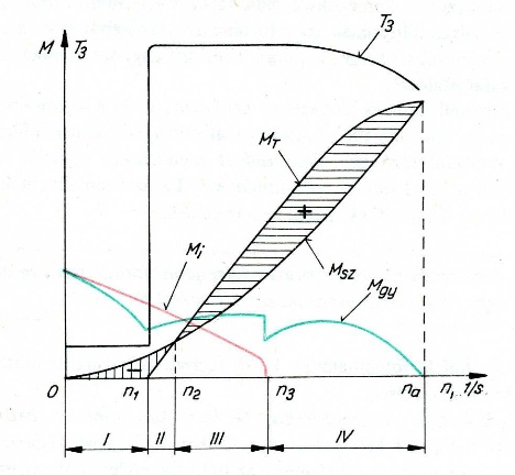
On he above figure, a gas turbine jet engine start-up curve is shown where the horizontal axis of the engine speed (n), the vertical axis is shown in the start-up torque (M), and after the turbine gas temperature (T3).
Symbols are as follows: Mi, the torque of the starting device, MT, the turbine torque, Msz, need to rotate the rotor torque, MGY, the acceleration torque, na, engine idle mode. Starting of the engine consist of IV. phases.
If the engine suffers a flameout, an airborne restart may be attempted. These starts typically happen one of a few ways:
- Crossbleed start
- APU start
- Windmilling start
The APU start is essentially the same process as above. The crossbleed start, which can also be done on the ground, merely substitutes a running engine at a high power setting to provide the bleed air for starting and is otherwise the same as above.
The interesting start is the windmilling start. The necessity for this means something bad has happened. To need a windmilling start, this means that there are no bleed air sources to supply the air turbine starter. This can mean that all engines are out and the APU is unavailable (BAD!), or merely that bleed valves to a shutdown engine have failed closed and are unable to be opened.
For the EMB-145 that I am familiar with, a windmilling start required descending at an airspeed between 260 KIAS and 320 KIAS and could not be attempted above FL250. In short, you hope that the mass flow through the engine is enough to spin the N2 compressor as the ATS would. With an N2 indication within the engines airstart envelope, you introduce spark and fuel and hope that the engine lights. In the worst case, if you too slow and unable to provide enough airflow prior to light off, the engine can quickly overtemp and be damaged. For this reason it is especially important to abort this kind of start as soon as an abnormality is detected.
Aircraft propeller:
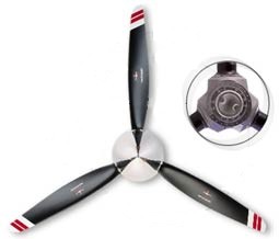
Thrust is the force that move the aircraft through the air.Thrust is generated by the propulsion system of the aircraft. There are different types of propulsion systems develop thrust in different ways, although it usually generated through some application of Newton's Third Law. Propeller is one of the propulsion system. The purpose of the propeller is to move the aircraft through the air. The propeller consist of two or more blades connected together by a hub. The hub serves to attach the blades to the engine shaft. The blades are made in the shape of an airfoil like wing of an aircraft. When the engine rotates the propeller blades, the blades produce lift. This lift is called thrust and moves the aircraft forward. most aircraft have propellers that pull the aircraft through the air. These are called tractor propellers. Some aircraft have propellers that push the aircraft. These are called pusher propellers.
Propellers may be classified as to whether the blade pitch is fixed or variable. The demands on the propeller differ according to circumstances. For example, in takeoffs and climbs more power is needed, and this can best be provided by low pitch. For speed at cruising altitude, high pitch will do the best job. A fixed-pitch propeller is a compromise. Propellers may be classified as to whether the blade pitch is fixed or variable. The demands on the propeller differ according to circumstances. For example, in takeoffs and climbs more power is needed, and this can best be provided by low pitch. For speed at cruising altitude, high pitch will do the best job.
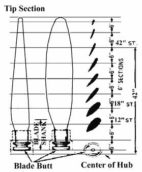
Blade Angle is formed between the face of an element and the plane of rotation. The blade angle throughout the length of the blade is not the same. The reason for placing the blade element sections at different angles is because the various sections of the blade travel at different speed. Each element must be designed as part of the blade to operate at its own best angle of attack to create thrust when revolving at its best design speed.
Types of propeller:
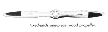
1. fixed pitch propellers ( Wooden Propellers, Metal Propellers )
Metall propellers
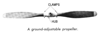
2. variable pitch propellers ( adjustable and controllable )
3. Constant speed propellers
Constant speed propellers
In modern aircraft, it is done automatically, and the propellers are referred to as constant-speed propellers. As power requirements vary, the pitch automatically changes, keeping the engine and the propeller operating at a constant rpm. If the rpm rate increases, as in a dive, a governor on the hydraulic system changes the blade pitch to a higher angle. This acts as a brake on the crankshaft. If the rpm rate decreases, as in a climb, the blade pitch is lowered and the crankshaft rpm can increase. The constant-speed propeller thus ensures that the pitch is always set at the most efficient angle so that the engine can run at a desired constant rpm regardless of altitude or forward speed.
Constant-speed propellers may have a full-feathering capability. Feathering means to turn the blade approximately parallel with the line of flight, thus equalizing the pressure on the face and back of the blade and stopping the propeller. Feathering is necessary if for some reason the propeller is not being driven by the engine and is wind-milling, a situation that can damage the engine and increase drag on the aircraft. Some controllable-pitch and constant-speed propellers also are capable of being reversed. This is done by rotating the blades to a negative or reverse pitch. Reversible propellers push air forward, reducing the required landing distance as well as reducing wear on tires and brakes.
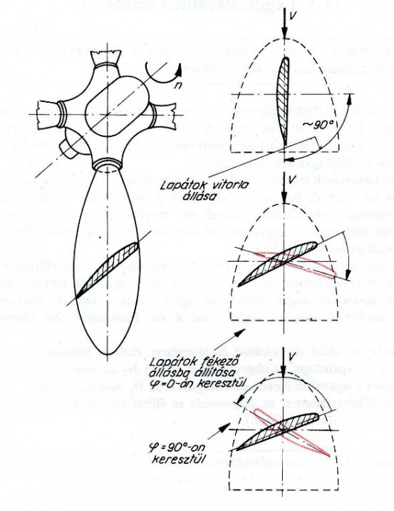
Windmilling and reverse propeller position
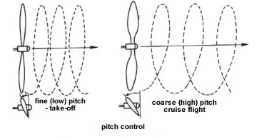
Take off and Cruise propeller position
Aircraft service ( Maintenance ) before take off:
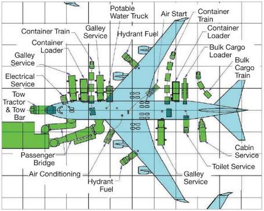
An airplane preparing to ride shall be equipped with a variety of service tasks to a number of services. Such versatility is shown in the figure, and in addition the following functions is required: the center of gravity calculations: ramp officers are carried out. In doing so, based on the number of flight passengers, baggage and cargoload, as well as the amount of fuel refueled and the location of all these experts calculate that the aircraft's center of gravity exact location. This flight safety and the lowest possible fuel consumption to ensure required.
Technical service:
performed before starting the receiving aircraft arriving aircraft, wheels splay of the initial inspection of the aircraft exterior, engine starting position towing / pushing, the removal of winter precipitation, and the protection against re-freezing.
The on-board maintenance team:
Out of airplane cabin cleaning - up after each flight. The several hundred-seat cabin, toilet and kitchen cleaning half a dozen in many cases, is only thirty minutes available. The air traffic control services are divided on the basis of the positions in scope. It is important to note that the existence of the positions and responsibilities of each airport is different. - Delivery clearance - responsible for issuing route permits. - Apron Service - hallway management. The task of issuing licenses to certain airport (engine start, push back, taxi) in a particular field. The scope and variety of license types, a variety of different airports. - Ground Control - responsible for airport traffic areas cover (taxiways, apron) in addition to the runways. Its task is to release the route permits are issued, engine start, push back and rolls for ordering the licenses, depending on the capacity of the airport from leaking other air traffic services (see Fig. Above) of operation. - Tower Control - Powers of the airport runways and the airport sector in the immediate vicinity of the CTZ supervision of, the task of these movements in the control of (take-off and landing, as well as the issuing of licenses relating to cross the tracks taxiing) and the CTZ-n activity in the supervision of small aircraft. - Traffic Director - task machines from the Placing to the path. It is only used in traffic. - Departure Control - responsible for the control of departing aircraft around the airport area. Larger used at airports. - Approach Control - responsible for the aircraft from initial guidance in the TMA. - Control Center - is responsible for traffic arriving, departing or transiting the guidance of a flight information zone, a GIS.
An International Air Transport Association survey estimates that 36–40 percent of damage to aircraft is from ramp and maintenance damage, sometimes called friendly foreign object damage (IATA, 1991).These areas are especially prone to damage and require robust material performance in these locations.
To determine the extent of groundhandling damage, 11 airline operators were queried for ground damage history during the years 1990 to 1993 (Boeing, 1994a). Of the 2,241 incidents reported, more than a third were from unknown causes.
Ramp and maintenance damage can represent significant costs to the airlines. The repair of a damaged component is only part of the cost. The airline also bears the cost of flight delay or cancellation and the effects on connections and aircraft rotations.
Aircraft Wing Shape:
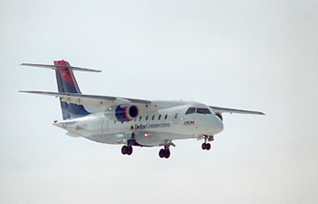
Low Wing :
Such as for example Boeing 747, 767, Airbus A310, and so on.
- The aircraft take off performance is better; compared with a high wing configuration; due to the ground effect.
- The pilot has a better higher-than-horizon view, since he/she is above the wing.
- The retraction system inside the wing is an option along with inside the fuselage.
- Landing gear is shorter if connected to the wing. This makes the landing gear lighter and requires less space inside the wing for retraction system. This will further make the wing structure lighter.
- In a light GA aircraft, the pilot can walk on the wing in order to get into the cockpit.
- The aircraft is lighter compared with a high wing structure.
- Aircraft frontal area is less.
- The application of wing strut is usually no longer an option for the wing structure. It implies that the aircraft structure is lighter since no strut is utilized.For the same reason, the aircraft drag is lower.
- The wing has less induced drag.
- It is more attractive to the eyes of a regular viewer.
- The aircraft has higher lateral control compared with a high wing configuration, since the aircraft has less lateral static stability, due to the fuselage contribution to the wing dihedral effect ( C lβ W ).
- The wing has less downwash on the tail, so the tail is more effective.
- The tail is lighter; compared with a high wing configuration.
- The wing drag is producing a nose-down pitching moment, so a low wing is longitudinally stabilizing. This is due to the lower position of the wing drag line relative to the aircraft center of gravity ( M Dcg >0 ).
- No wing strut.
Mid Wing:
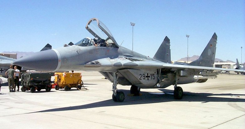
Such as for example MIG-29, az F-16 Fighting Falcon and so on.
Features of the mid-wing configuration stand somewhat between features of high-wing configuration and features of low-wing configuration. The major difference lies in the necessity to cut the wing spar in two half in order to save the space inside the fuselage.
- The aircraft structure is heavier, due to the necessity of reinforcing wing root at the intersection with the fuselage.
- The mid wing is more expensive compared with high and low-wing configurations.
- The mid wing is more attractive compared with two other configurations.
- The mid wing is aerodynamically streamliner compared with two other configurations.
- The strut is usually not used to reinforce the wing structure.
- The pilot can get into the cockpit using the wing as a step in a small GA aircraft.
- The mid-wing has less interference drag than low-wing and high-wing.
High Wing:
Such as for example C-130 Hercules, Cessna 208, Fokker 50, BAE Sea Harrier and so on.
The high wing configuration has several advantages and disadvantages that make it suitable for some flight operations, but unsuitable for other flight missions.
- Eases and facilitates the loading and unloading of loads and cargo into and out of cargo aircraft. For instance, truck and other load lifter vehicles can easily move around aircraft and under the wing without anxiety of the hitting and breaking the wing.
- Facilitates the installation of engine on the wing, since the engine (and propeller) clearance is higher (and safer), compared with low wing configuration.
- Saves the wing from high temperature exit gasses in a VTOL 2 aircraft (e.g. Harrier GR9 and BAe Sea Harrier ). The reason is that the hot gasses are bouncing back when they hit the ground, so they wash the wing afterward. Even with a high wing, this will severely reduce the lift of the wing structure. Thus, the higher the wing is the farther the wing from hot gasses.
- Facilitates the installation of strut. This is based on the fact that a strut (rod or tube) can handle higher tensile stress compared with the compression stress. In a high wing, the strut has to withstand tensile stress, while the strut in a low wing must bear the compression stress.
- Facilitates the taking off and landing from sea. In a sea-based or an amphibian aircraft, during a take-off operation, water will splash around and will high the aircraft. An engine installed on a high wing will receive less water compared with a low wing. Thus, the possibility of engine shut-off is much less.
- Facilitates the aircraft control for a hang glider pilot, since the aircraft center of gravity is lower than the wing.
- Increases the dihedral effect (C lβ ). It makes the aircraft laterally more stable. The reason lies in the higher contribution of the fuselage to the wing dihedral effect (C lβw ).
- The wing will produce more lift compared with mid and low wing, since two parts of the wing are attached at least on the top part. For the same reason, the aircraft will have lower stall speed, since CLmax will be higher.
- The pilot has better view in lower-than-horizon. A fighter pilot has a full view under the aircraft.
- For an engine that is installed under the wing, there is less possibility of sand and debris to enter engine and damage the blades and propellers.
- There is a lower possibility of human accident to hit the propeller and be pulled to the engine inlet. In few rare accidents, several careless people has died (hit the rotating propeller or pulled into the jet engine inlet).
- The aerodynamic shape of the fuselage lower section can be smoother.
- There is more space inside fuselage for cargo, luggage or passenger.
- The wing drag is producing a nose-up pitching moment, so it is longitudinally destabilizing. This is due to the higher location of wing drag line relative to the aircraft center of gravity ( M Dcg >0 ).
Inverted gull wing:
Inverted gull wing aircraft have a wing configuration in which the inboard wing section (i.e. adjoining the fuselage) is set at an anhedral angle, i.e. the outer end is lower than the wing root, while the outboard section is set at an dihedral angle with the outer end (usually the wingtip) higher than the inner end. Seen from the front, this wing configuration has an elongated 'W'-shape.
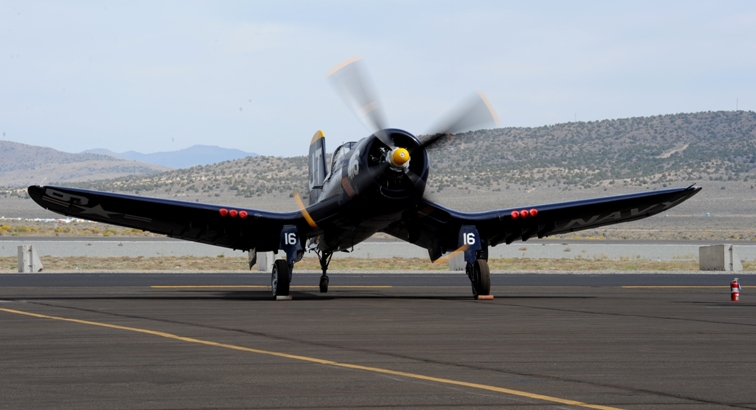
Gull wing:
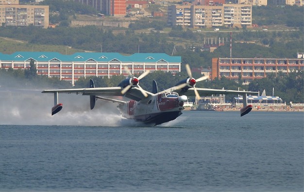
Some examples, Be-12 seaplane, Dornier Do 26, PZL P.11 and so on.
The gull wing is an aircraft's wing configuration with a prominent bend in the wing somewhere along the span, generally near the wing root. Its name is derived from the seabirds which it resembles. It has been incorporated in aircraft for many reasons. The gull wing was first seen on a glider in 1921. The gull wing design found its way into seaplanes by the early 1930s. As engine power increased, so did the need for large propellers that could effectively convert power to thrust. The gull wing allowed designers to ensure adequate propeller tip clearance over the water by placing the engines on the highest point of the wing.
Dihedral wing:

For example Boeing 767.
Wing Dihedral is the upward angle of an aircraft's wing, from the wing root to the wing tip. The amount of dihedral determines the amount of inherent stability along the roll axis. Although an increase of dihedral will increase inherent stability, it will also decrease lift, increase drag, and decreased the axial roll rate. As roll stability is increased, an aircraft will naturally return to its original position if it is subject to a brief or slight roll displacement. Most large airliner wings are designed withdihedral.
Anhedral wing:
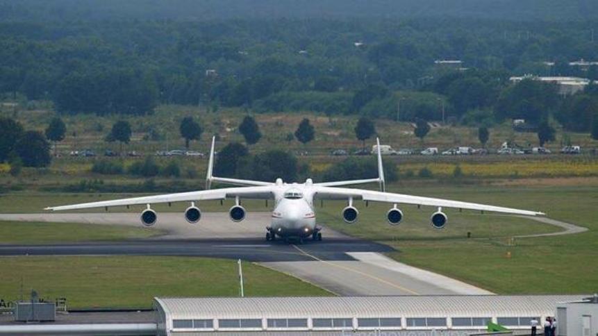
For example TU-154, An-225 see above figure, B52, An-74TK-300, and so on.
Anhedral wings will induce roll instability and improve roll maneuverability. In a large/heavy airplane with a high-wing configuration there is usually excess roll stability, so this type of wings can be pretty common. Both the high wing configuration and wing sweep contribute a negative sideslip-induced rolling, and anhedral is necessary to limit this moment. If sideslip causes strong rolling, the aircraft will have a tendency to duch roll.
But in certain cases, the high-wing plus pronounced anhedrial design has won out for some heavy cargo hauling designs, and is particularly popular with military where they may have to operate out of dirt runways and need to get the wings up away from the ground, and where short landing gear is desirable.
Angle of attack:
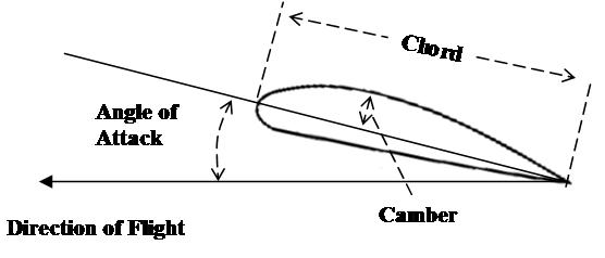
The Angle of Attack is the angle at which relative wind meets an Aerofoil. It is the angle formed by the Chord of the aerofoil and the direction of the relative wind or the vector representing the relative motion between the aircraft and the atmosphere. The angle of attack can be simply described as the difference between where a wing is pointing and where it is going.
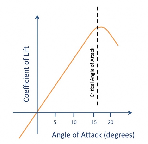
An increase in angle of attack results in an increase in lift and induced drag, up to a point. Too high an angle of attack (usually around 17 degrees) and the airflow across the upper surface of the aerofoil becomes detached, resulting in a loss of lift, otherwise known as a Stall ( Critical Angle of Attack ).
Approach Control ( APP ):
In order to improve the management of departures and arrivals at larger airports, terminal areas (TMA) have been defined wherein a specific air traffic control service is provided: approach control (APP). These controlled areas encompass the CTRs and can, in some cases, serve several airports at the same time. The Brussels Terminal Area (Brussels TMA) for instance, serves the airports of Antwerp, Brussels as well as the Chièvres military base.
Approach Controllers provide all ATC services to aircraft moving within the terminal area of the airport (TMA). Traffic flow is broadly divided into departures, arrivals and overflights.
When an aircraft, after take-off, leaves the airport surroundings, the air controller of the control tower hands it over to a departure controller who is located at APP. Assisted by the radar, the latter will guide the aircraft through the flows of approaching traffic and will manage the initial part of its ascent.
Conversely, when an aircraft abandons its cruising level and begins its descent, the “en-route” controller hands it over to an “arrival” controller at an appropriate altitude and a specific point. The “arrival” controller, like his colleague the “departure” controller, is located at APP.
An “arrival” controller’s task is to manage descents and to align the various approaching aircraft on the runway axis, hereby respecting the safety distances. Once the aircraft are in their “final” alignment, the “arrival” controller hands them over to the air controller in the tower (TWR), who will authorize their landing.
Belgocontrol has two approach services (APP), one at CANAC (Computer Assisted National Air traffic Control Centre) in Steenokkerzeel and the other at Ostend Airport.
Aquaplaning:
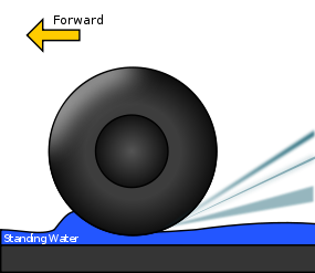
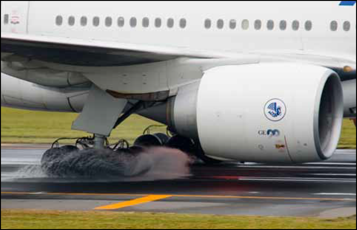
Aquaplaning is a condition that can exist when an aircraft is landed on a runway surface contaminated with standing water, slush, and/or wet snow. Aquaplaning can have serious adverse effects on ground controllability and braking efficiency. The three basic types of aquaplaning are dynamic aquaplaning, reverted rubber aquaplaning, and viscous aquaplaning. Any one of the three can render an aircraft partially or totally uncontrollable anytime during the landing roll. Aquaplaning may reduce the effectiveness of wheel braking in aircraft onlanding or aborting a takeoff, when it can cause the aircraft to run off the end of the runway.
However this can be prevented by grooves on runways. This was initially developed by NASA for space shuttles landing in heavy rain. It has since been adopted by most major airports around the world. Thin grooves are cut in the concrete which allows for water to be dissipated and further reduces the potential to aquaplane.
Aquaplaning types are the follows: Viscous, Dynamic and Reducing risk.
Viscous aquaplaning is due to the viscous properties of water. A thin film of fluid no more than 0.025 mm in depth is all that is needed. The tire cannot penetrate the fluid and the tire rolls on top of the film.
Dynamic aquaplaning is a relatively high-speed phenomenon that occurs when there is a film of water on the runway that is at least 1/10 inch (2.5 mm) deep. As the speed of the aircraft and the depth of the water increase, the water layer builds up an increasing resistance to displacement, resulting in the formation of a wedge of water beneath the tire.
Reverted rubber (steam) aquaplaning occurs during heavy braking that results in a prolonged locked-wheel skid. Only a thin film of water on the runway is required to facilitate this type of aquaplaning.
Aquaplaning poses a serious risk to aviation safety during heavy rain, and it is most frequent in the tropics. It has been a contributing factor in some aircraft incidents and accidents. Accurate information on water level thickness on the runway could help pilots to make better decisions on how to land safely. Until recently, a comprehensive and reliable method for assessing the thickness of the water layer has not been available.
Aircraft can use its tire brakes, flaps, spoilers and reverse thrust to decelerate its speed, for example. These methods are usually enough, but unexpected conditions during landing may result in their ineffective use. As grooves across the runway surface help drain excess water, they may decrease the risk of a landing aircraft ending up in an aquaplaning situation. However, a gooved runway won’t completely eliminate the risk in heavy rain. Information on water layer thickness on the runway can be gathered using different methods. One option is to take direct measurements using runway surface sensors.
Atmosphere:
The atmosphere of Earth is mostly composed of nitrogen. It also contains oxygenused by most organism for respiration and carbon dioxide used by plants, algae and cyanobacteria for photosynthesis. It protects living organisms from genetic damage by solar ultraviolet radiation, solar wind and cosmic rays. Its current composition is the product of billions of years of biochemical modification of the paleoatmosphere by living organisms.
The term stellar atmosphere describes the outer region of a star, and typically includes the portion starting from the opaque photosphere outwards. Stars with sufficiently low temperatures may form compound molecules in their outer atmosphere.
The thermosphere ranges in altitude from 90 km to 600+ km. It is a realm of meteors, auroras and satellites, which skim through the thermosphere as they circle Earth. It is also where solar radiation makes first contact with our planet. The thermosphere intercepts extreme ultraviolet (EUV) photons from the sun before they can reach the ground. When solar activity is high, solar EUV warms the thermosphere, causing it to puff up like a marshmallow held over a camp fire. (This heating can raise temperatures as high as 1400 K—hence the name thermosphere.) When solar activity is low, the opposite happens.
Because satellites feel aerodynamic drag when they move through the thermosphere, it is possible to monitor conditions there by watching satellites decay. He analyzed the decay rates of more than 5000 satellites ranging in altitude between 200 and 600 km and ranging in time between 1967 and 2010. This provided a unique space-time sampling of thermospheric density, temperature, and pressure covering almost the entire Space Age. In this way he discovered that the thermospheric collapse of 2008-2009 was not only bigger than any previous collapse, but also bigger than the sun alone could explain.
One possible explanation is carbon dioxide (CO2).
When carbon dioxide gets into the thermosphere, it acts as a coolant, shedding heat via infrared radiation. It is widely-known that CO2 levels have been increasing in Earth's atmosphere. Extra CO2 in the thermosphere could have magnified the cooling action of solar minimum.
Atmospheric pressure:
The weight of the air pressing down on the Earth, the ocean and on the air below causes air pressure. Earth's gravity, of course, causes the downward force that we know as "weight." Since the pressure depends upon the amount of air above the point where you're measuring the pressure, the pressure decreases as you go higher.
Air pressure is related to its density, which is related to the air's temperature and height above the Earth's surface. Air pressure changes with the weather. In fact, it's one of the most important factors that determines what the weather is like.
The National Weather Service reports surface air pressure in inches of mercury, while air pressure aloft is reported in millibars, also known as hectopascals (hPa). Scientists generally use hectopascals to measure air pressure.
In the rest of the world, measurements are usually given in hectopascals, although you'll sometimes see them in centimeters of mercury, especially on older barometers.
The term hectopascals is replacing the term millibars. The hectopascal is a direct measure of pressure, like pounds per square inch, but in the metric system. Since the measurement is in the metric system, 1,000 millibars equal one bar. A bar is a force of 100,000 Newtons acting on a square meter, which is too large of a unit to be a convenient measure of Earth's air pressure.
Inches of mercury and centimeters of mercury measure how high the pressure pushes the mercury in a barometer. The use of direct pressure measurements goes back to the late 19th century. This was when the Norwegian meteorologist Vilhelm Bjerknes, a leader in making meteorology a mathematical science, urged weather services to use direct pressure measurements because they can be used in the formulas that describe the weather, unlike measures of the height of the mercury in a barometer.
Changes in air pressure, especially rather quick changes, can affect your body. The most obvious of these are the discomfort or even pain you feel in your ears when your gain or lose altitude rather quickly, such as in an aircraft, or even a fast elevator that goes up or down several floors.
Air pressure changes can also be felt in other ways.
Air pressure corrections
When you read a barometer the reading directly from it is the "station pressure."
Two things affect the barometer's reading, the high or low air pressure caused by weather, and the air pressure caused by the station's elevation, or how high it is above sea level.
No matter what weather systems are doing, the air's pressure decreases with height. If you're trying to draw a weather map of air pressure patterns, you need a way to remove the effects of the station's elevation. That is, you want to see what the pressure would be at the station if it were at sea level. Otherwise, all high-elevation locations would be mapped as having low pressure.
You need to calculate, sea-level pressure, which is defined as: "A pressure value obtained by the theoretical reduction of barometric pressure to sea level. Where the Earth's surface is above sea level, it is assumed that the atmosphere extends to sea level below the station and that the properties of that hypothetical atmosphere are related to conditions observed at the station."
To do this, you have to take into account the barometric reading at the station, the elevation above sea level, and the temperature.
Another kind of barometric reading is the altimeter setting, which aircraft use. It's defined as: "The pressure value to which an aircraft altimeter scale is set so that it will indicate the altitude above mean sea level of an aircraft on the ground at the location for which the value was determined." For it, all you need is the station pressure and the elevation, you can ignore the temperature.
How pressure decreases with altitude
As you go higher in the air, the atmospheric pressure decreases.
The exact pressure at a particular altitude depends of weather conditions, but a couple of approximations and a formula can give you a general idea of how pressure decreases with altitude.
A rule of thumb for the altimeter correction is that the pressure drops about 1 inch of mercury for each 1,000 foot altitude gain. If you're using millibars, the correction is 1 millibar for each 8 meters of altitude gain. These rules work quite well for elevations or altitudes of less than two or three thousand feet.
The standard atmosphere is a table giving values of air pressure, temperature and air density for various altitudes from the ground up. You can think of these values as averages for the entire Earth over the course of a year.
Autopilot:
Airbus, A 340 Autopilot panel
It is what the name suggests—the autopilot flies the airplane without the human pilots controlling "hands on." Basically it is a computer that is running very, very fast. It can almost fly the plane completely between takeoff and landing. The autopilot system relies on a series of sensors around the aircraft that pick up information like speed, altitude and turbulence. That data are ingested into the computer, which then makes the necessary changes. Basically, it can do almost everything a pilot can do. Key phrase: almost everything.
Before takeoff, the pilot will enter the route into the computer, giving it a start and end position and exactly how to get there. Throughout that route there are a series of points that the computer will note, each having its own speed and altitude. The autopilot does not steer the airplane on the ground or taxi the plane at the gate. Generally, the pilot will handle takeoff and then initiate the autopilot to take over for most of the flight. In some newer aircraft models, autopilot systems will even land the plane.
Aviation regulations vary between countries, but in the U.S., at least two crew members must remain in the cockpit at all times. From a flying perspective, the pilot or the co-pilot must remain at the controls to keep an eye on the computer to make sure everything is running smoothly. Occasionally, the autopilot will disengage itself in the event of extreme turbulence, for example, at which the pilot will be alerted to take over control of the plane. But standard procedure for most airlines is the use of automation for much of the flight. The general guidance given to pilots is, "Let the computer do it because it can do a better job than a person." Just think about how hard it would be for a person to concentrate for long stretches of time while flying hands-on.
But that guidance should not be taken lightly. A pilot must still be completely aware of exactly what it is the autopilot system is or isn't doing. Case in point: in 2013 Asiana Airlines Flight 214 crashed while landing at San Francisco International Airport in what was cited as an autopilot issue. The pilots assumed the autopilot was doing something it actually wasn't doing, on the safe but highly automated Boeing 777. Automation is great but if there is a misunderstanding between the crew and the automation system, it can be dangerous.
In that way, autopilot is similar to a car's cruise control. It can take over when you need it to, but you still have to be aware of what the car is doing and where it is going.
"The auto flying system does not fly the airplane. "The pilots fly the plane through the automation."
The cockpit can still be a very busy place. Pilots are consistently having to command, manipulate and manage various parts of the computer system which requires their full attention. In addition about 99 percent of landings are manual and 100 percent of all takeoffs must be done manually by the pilot. There is not yet such a thing as an automated takeoff.
Auxiliary Power Unit ( APU ):
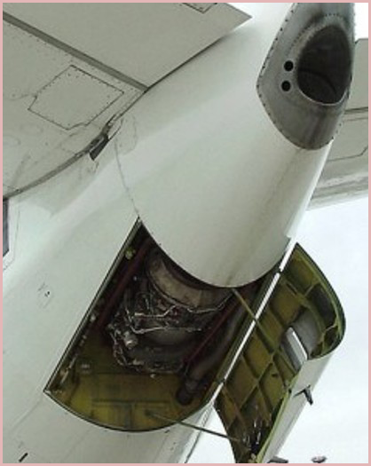
If you look closely at commercial aircraft, you might notice something that looks a bit like an extra engine. Consider the CRJ-900 for example. It clearly has only two engines, but take a look at the tail. It has an additional jetpipe which surely resembles a third engine. So what’s the deal? Hold onto your butts: it is a third engine. In fact, it’s a very special kind of engine found on airliners and some corporate jets called an Auxiliary Power Unit, or APU. The APU is an internal and highly automated powerplant that provides backup power to a number of systems and provides pressurized air for main engine starting. As you aviation-savvy readers already know, redundancy is the name of the game, and an APU provides plenty. A typical APU spins an electrical generator that is capable of providing electrical power to most (or all) onboard systems in the event of a dual engine or primary generator failure. Furthermore, bleed air is pulled off the APU’s compressor to provide hot pressurized air for use in air conditioning and pressurization systems. Under normal circumstances, APU’s are used by flight crews to aid in engine starting and to provide air conditioning for passenger (and crew!) comfort on the ground. Typically, the APU will be shut down at some time before takeoff or as part of the climb checklist, effectively transferring all electrical and air conditioning systems to the main engines. In the interest of safety, APU’s are heavily isolated in modern aircraft. The APU is enclosed in a fireproof titanium box and features its own semi-automated fire detection and fire extinguishing systems, completely separate from other aircraft systems. In theory, the APU could burn itself to a cinder without endangering the passengers or crew, which is a comforting thought.
Aircraft are equipped with a number of power generation systems including both primary and redundant backup systems to continue supplying power to vital equipment in an emergency. Primary power is usually provided by AC generators directly connected to the jet engines. Commercial aircraft and many military planes are also equipped with an auxiliary power unit (APU), which is essentially a miniature jet engine that provides an additional power source. The APU is always in operation to supplement the primary power supply or replace it in case of engine failure. If the APU also fails, many aircraft carry an additional ram air turbine (RAT) that can be deployed when needed to provide emergency power. The purpose of a RAT is to keep critical systems operating long enough to land safely.
Axial Compressor:
The basic components of an axial flow compressor are a rotor and stator, the former carrying the moving blades and the latter the stationary rows of blades. The stationary blades convert the kinetic energy of the fluid into pressure energy, and also redirect the flow into an angle suitable for entry to the next row of moving blades. Each stage will consist of one rotor row followed by a stator row, but it is usual to provide a row of so called inlet guide vanes. This is an additional stator row upstream of the first stage in the compressor and serves to direct the axially approaching flow correctly into the first row of rotating blades. For a compressor, a row of rotor blades followed by a row of stator blades is called a stage. Two forms of rotor have been taken up, namely drum type and disk type. A disk type rotor illustrated in Figure 1. The disk type is used where consideration of low weight is most important. There is a contraction of the flow annulus from the low to the high pressure end of the compressor. This is necessary to maintain the axial velocity at a reasonably constant level throughout the length of the compressor despite the increase in density of air. Figure 2. illustrate flow through compressor stages. In an axial compressor, the flow rate tends to be high and pressure rise per stage is low. It also maintains fairly high efficiency.
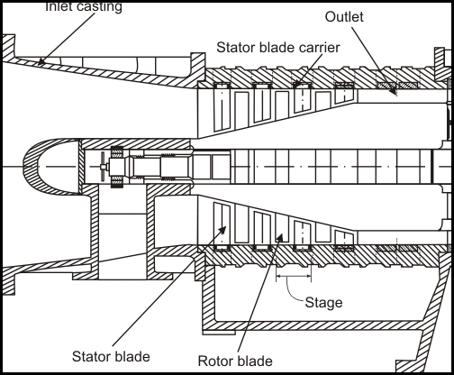
Figure 1. Disk type axial flow compressor
The basic principle of acceleration of the working fluid, followed by diffusion to convert acquired kinetic energy into a pressure rise, is applied in the axial compressor. The flow is considered as occurring in a tangential plane at the mean blade height where the blade peripheral velocity is U . This two dimensional approach means that in general the flow velocity will have two components, one axial and one peripheral denoted by subscript w , implying a whirl velocity. It is first assumed that the air approaches the rotor blades with an absolute velocity,  , at and angle
  to the axial direction. In combination with the peripheral velocity U of the blades, its relative velocity will be
  at and angle
  as shown in the upper velocity triangle (Figure 3.). After passing through the diverging passages formed between the rotor blades which do work on the air and increase its absolute velocity, the air will emerge with the relative velocity of
  at angle
  which is less than
  . This turning of air towards the axial direction is, as previously mentioned, necessary to provide an increase in the effective flow area and is brought about by the camber of the blades. Since
  is less than
  due to diffusion, some pressure rise has been accomplished in the rotor. The velocity
  in combination with U gives the absolute velocity
  at the exit from the rotor at an angle
  to the axial direction. The air then passes through the passages formed by the stator blades where it is further diffused to velocity
  at an angle
  which in most designs equals to
  so that it is prepared for entry to next stage. Here again, the turning of the air towards the axial direction is brought about by the camber of the blades.
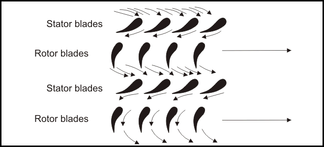
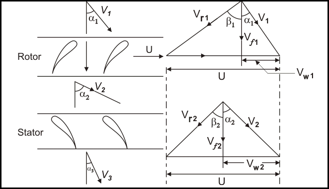
Like distance, direction is difficult to measure on maps because of the distortion produced by projection systems. However, this distortion is quite small on maps with scales larger than 1:125,000. Direction is usually measured relative to the location of North or South Pole. Directions determined from these locations are said to be relative to True North or True South. The magnetic poles can also be used to measure direction. However, these points on the Earth are located in spatially different spots from the geographic North and South Pole. The North Magnetic Pole is located at 78.3° North, 104.0° West near Ellef Ringnes Island, Canada. In the Southern Hemisphere, the South Magnetic Pole is located in Commonwealth Day, Antarctica and has a geographical location of 65° South, 139° East. The magnetic poles are also not fixed overtime and shift their spatial position overtime.
Topographic maps normally have a declination diagram drawn on them (Figure 1.). On Northern Hemisphere maps, declination diagrams describe the angular difference between Magnetic North and True North. On the map, the angle of True North is parallel to the depicted lines of longitude. Declination diagrams also show the direction of Grid North. Grid North is an angle that is parallel to the easting lines found on the Universal Transverse Mercator (UTM) grid system (Figure 1,).
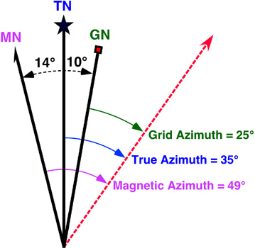
Figure 1.: This declination diagram describes the angular difference between Grid, True, and Magnetic North. This illustration also shows how angles are measured relative grid, true, and magnetic azimuth.
In the field, the direction of features is often determined by a magnetic compass which measures angles relative to Magnetic North. Using the declination diagram found on a map, individuals can convert their field measures of magnetic direction into directions that are relative to either Grid or True North.
Barometric pressure:
The air pressure Tori Celli (Evangelista Torricelli, Faenza, 1608 .. - Florence, 1647, Italian physicist and mathematician) had discovered. The air pressure is none other than the air pressure located above those in the lower layers (called static pressure). So we go higher up, the more air is "thinner" (equal volume to weight less), so the pressure is reduced. Contractual value of 1013.25 mbar air pressure at sea level. This of course this can only be a general value, depending on weather, more or less. The pressure measurement is carried out in the circular of the aviation and pressure gauges. The earth's atmosphere layer of different heights was designated by different names: a height of 0-10 km Troposphere (The weather is happening here), 10-40 km altitude stratosphere 40 km above the Ionosphere. The gravity of the atmosphere of the earth's surface and objects on the surface rests. The pressure per unit area can be called air pressure. The barometer measuring air pressure. The air is the air pressure at sea level (ill. The so-called. Deep fields) is the largest, rising up is reduced. The explanation that there are fewer layers of air below those in the press. The air pressure decreases logarithmically with altitude. Thus, the air layer is strongly compressed, layer 99% of a height of up to about 36km away. The decrease in the vertical pressure gradient is characterized Bárikus altitude. The "bárikus" elevation gradient determines how many mbar air pressure decrease corresponds to the amount of variation in height of each layer.
Bernoulli principle:
Bernoulli principle states that as the speed of a moving fluid increases, the pressure within the fluid decreases. Fluid can be in liquid or gaseous state. The animation shows the lift produced as a result of the low pressure created on the upper surface of the air-plane's wings compared to the pressure on the wing's lower surfaces,causing the wing to be lifted upward. This uplifting is mainly on the basis of Bernoulli's principle.
Bird Strike:
The collisions of birds (Bird Strike) in many cases are caused by damage to the aircraft, but many accidents and even more disaster also caused world-wide. Collisions with birds mostly at airports or in close proximity to happen. The aircraft take-off and landing phase of the most vulnerable, since both the speed and height, as well as maneuverability in respect of some of the reserve at this stage of the flight. The collision damaged the aircraft's engines, government bodies and the tribes, and these failures may be extremely difficult situation of the aircraft. Engine manufacturers for instance to test the engines that frozen birds are shot into the engine unit with, so his assessment of the reliability of the engine and the damage caused by the collision. The Liszt Ferenc International Airport ( In Budapest, Hungary ) airspace is a plethora of native bird species, and among these are the most dangerous to airplanes and birds of prey the kestrel, because the diet is the main guy that lives large population of green areas of the airport.
Defending the earth long grass technology, which is made more difficult for birds of prey hunting, acoustic protection, sound cannons, an acoustic control of sound imitation, visual protection scarecrow, planting trees alkalmazása- so the birds are not the lighting devices monitor the prey animals, falconry.
Defending the air: the pilots to apply preventive techniques, such as - during the height of 3000 meters, the maximum speed limit - operated lights in the lower altitudes - the use of on-board radar equipment. The following video shows how serious the consequences of bird strikes:
BOEING COMPANY:
The Boeing company in 1916, William Edward Boeing (the name Boeing in 1900 from Yale University enrollment anglicized. In 1934, the company the US government dismembered because of antitrust proceedings were instituted against him. After that he retired, and in 1956 died in Seattle in heart attack) and George Conrad Westerveld was founded in Seattle, but today the name of the "Boeing Airplane Company" in 1917 picked up.
William Edward Boeing portrait in1929
The headquarter of the Boeing company is in Chicago, and the aircrafts is produced in Seattle, in Washington state ( also in two districts of Everett and Renton ). The 2000 onwards, the company is also active in the field of space research. Over time, Boeing was established the world's leading civil aircraft manufacturer itself, while Airbus has overtaken. The company made a lot of successful civil aircraft "families", like in the early 70s, the 737 (8470 to the present day pieces were made, it was amazingly successful models), the 747- and (until 1500 it was produced from it, and it can be stated that to this day is a miracle aircraft, with its unique parameters), and the pride of today's 787 Dreamliner. But I could go on to other types of success, such as 727, 767, 777 and so on.
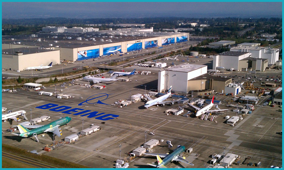
Boeing company in Everett
Bypass ratio:
The bypass ratio (BPR) of a turbofan engine is the ratio between the mass flow rate of air drawn through the fan disk that bypasses the engine core (un-combusted air) to the mass flow rate passing through the engine core. For example, a 10:1 bypass ratio means that 10 kg of air passes around the core for every 1 kg of air passing through the core.
There are ramjet engines, low bypass (zero bypass) engines, medium-bypass engines, high- bypass engine sand ultrahigh-bypass engines.
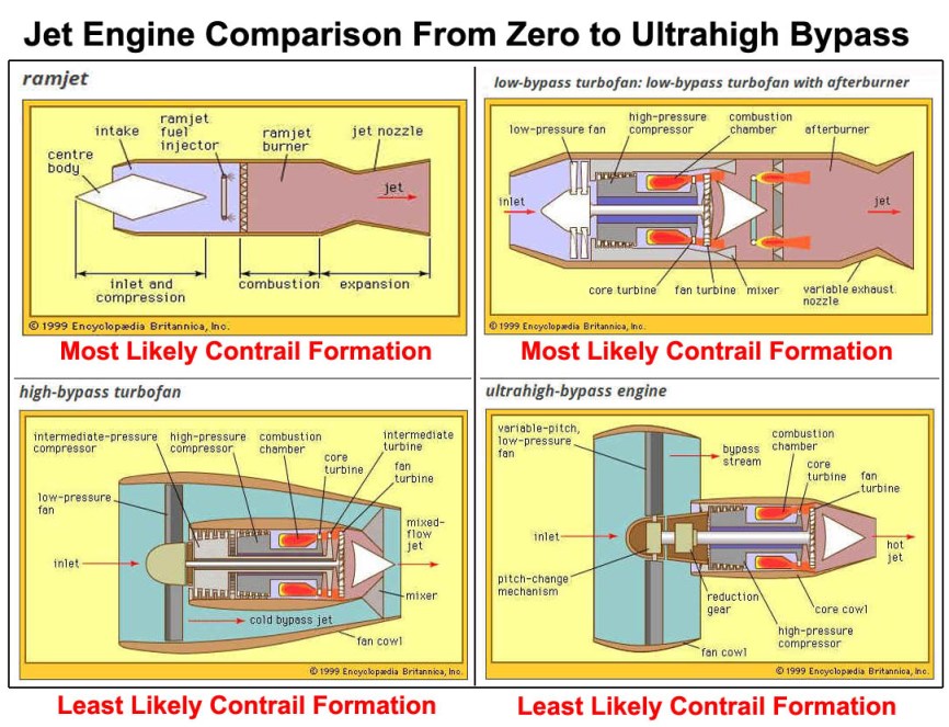
Ramjats and supersonic combustion ramjets:
As has been seen, ram pressure plays an increasingly important role in the thermodynamic cycle of power and thrust generation of the jet engine at supersonic flight speeds. For flight speeds above Mach 2.5 or 3, the ram-pressure ratio becomes so high that a turbocompressor is no longer necessary for efficient thrust generation. Indeed, the pressure ratio eventually rises to such high values that the associated high ram temperatures make it difficult or impossible to place high-speed rotating machinery in the flow path without prohibitive amounts of cooling provision. This combination of circumstances gives rise to the ramjat, a jet engine in which the pressure increase is attributable only to the ram effect of the high flight speed; no turbomachinery is involved, and the main thrust producer is an afterburner.
Ramjets are lightweight and simple power plants, making them ideal candidates for supersonic flight vehicles that are launched from other flight vehicles at extremely high speed. They are less suitable for use in vehicles that must be sufficiently self-powered for subsonic takeoff, climb, and acceleration to supersonic flight speed; the subsonic ram pressure is insufficient to produce any reasonable amount of thrust, and so alternative propulsion devices must be provided.
In the flight regime of Mach 4 or 5, it is usually efficient to decelerate the inlet airstream to subsonic velocity before it enters the combustion system. At still higher Mach numbers, such deceleration becomes more difficult and costly in terms of pressure losses, and it is necessary to make provision for the combustion chamber to burn its fuel in the supersonic airstream. Such specialized ramjets are called scramjets (for supersonic combustion ramjets) and are projected to be fueled by a cryogenically liquified gas (e.g., hydrogen or methane) instead of a liquid hydrocarbon. The primary reason for doing so is to exploit the greater heat release per unit weight of fuels that have a higher ratio of hydrogen to carbon atoms than ordinary fractions of petroleum even though this gain is partly negated by the higher volume per unit of heat release of those same fuels. Another incentive for employing a very cold fuel is that it may be used as a heat sink for cooling a very high-speed (and hence very hot) engine and aircraft structure. The scramjat has an unusual feature: the inlet deceleration and exhaust acceleration occur largely outside the enclosed engine inlet and exhaust ducts against external aircraft surfaces in front of and to the rear of the engine. In effect, the engine itself is little more than a sophisticated supersonic combustion chamber.
Low-bypass engines:
In the next higher regime of aircraft flight speed, the low supersonic range from Mach numbers above 1 up to 2 or 3, one finds the application of the simple turbojet (with no bypass stream) and the low-bypass turbofan engine (with a bypass ratio up to 2).
Although the low-bypass turbofan has the same general appearance as a turbofan with a larger bypass ratio, certain special features are unique to low-bypass engines. The lower total flow in the fan generally involves a higher fan pressure ratio (for equivalent amounts of energy available from the drive turbine), and so such a fan usually has more than one (i.e., two or three) turbocompressor stages. Engines designed to operate at the low supersonic range generally have insufficient thrust in other flight regimes or modes where they must operate for short durations, as, for instance, acceleration through transonic speed, takeoff from high-altitude airports under conditions of extremely high temperatures and high gross weight, or combat maneuvers at high supersonic flight speed. Rather than installing a larger engine to meet these requirements, it is more effective to add an afterburner to a turbofan engine as a means of thrust augmentation. The afterburner is a secondary combustion system that operates in the exhaust stream of the engine before the stream is introduced into the exhaust nozzle. Such a device is not as fuel-efficient as the main turbofan section of the engine because heat addition occurs at a lower pressure than in the main burner. The afterburner, however, is relatively simple and lightweight, since it does not contain any rotating machinery. For the same reason, it may be operated to a much higher discharge temperature (typically 1,760 °C), so that it is capable of augmenting the thrust of the turbofan by as much as 50 percent.
The afterburner in a turbofan usually requires a mixer for mixing the relatively cool bypass air with the hot core stream; the cooler air is otherwise difficult to burn in the low-pressure environment of an afterburner. Also, in both the turbojet and the turbofan with an afterburner, the exhaust nozzle must have a variable throat area to accommodate the large variations in volumetric flow rate between the very hot exhaust stream from the operating afterburner and the cooler airstream discharged from the engine when the afterburner is not in use. Engines intended for supersonic flight generally have a much lower compression-pressure ratio than higher-bypass machines intended for subsonic or transonic operation. A major contributor to this tendency is the additional pressure ratio developed in the engine’s inlet as it slows down or diffuses the very high-speed airstream that is ingested as the engine’s working fluid—the ram effect. At transonic flight speed this pressure ratio is almost 2:1, so that the engine’s compressor may be built to provide that much less pressure where peak pressure is otherwise limiting.
Early generations of jet-propelled aircraft in this low supersonic flight regime were powered by turbojet engines, but subsequent generations built for the same flight regime have largely been equipped with low-bypass turbofans. This substitution of engine type was undertaken primarily because such aircraft expend a great deal of their fuel at subsonic flight speed (e.g., in takeoff, climb, loiter, acceleration, approach, and landing), where the turbofan provides an advantage in propulsive efficiency.
Military combat aircraft usually use engines with low bypass ratios to compromise between fuel economy and the requirements of combat: high power-to-weight ratios, supersonic performance, and the ability to use afterburners, all of which are more compatible with low bypass engines.
Medium-bypass turbofans, high-bypass turbofans, and ultrahigh-bypass engines:
Moving up in the spectrum of flight speeds to the transonic regime—Mach numbers from 0.75 to 0.9—the most common engine configurations are turbofan engines, such as those shown in Figures 4 and 5. In a turbofan, only a part of the gas horsepower generated by the core is extracted to drive a propulsor, which usually consists of a single low-pressure-ratio, shrouded turbocompression stage. The fan is generally placed in front of the core inlet so that the air entering the core first passes through the fan and is partially compressed by it. Most of the air, however, bypasses the core (hence the designation bypass stream) and goes directly to an exhaust nozzle. The core stream, with some modest fraction of the gas horsepower remaining (not extracted to drive the fan) proceeds directly to its own exhaust nozzle.
A key parameter for classifying the turbofan is its bypass ratio defined as the ratio of the mass flow rate of the bypass stream to the mass flow rate entering the core. Since the highest propulsion efficiencies are obtained by the engines with the highest bypass ratios, one would expect to find all engines of that design in this flight speed regime. (Some of the variation derives from historical evolution.) In actuality, however, one finds engines with a broad spectrum of bypass ratios, including medium-bypass engines (with bypass ratios from 2 to 4), high-bypass engines (with bypass ratios from 5 to 8), and ultrahigh-bypass engines, so-called UBEs (with bypass ratios from 9 to 15 or higher). A whole generation of low- and medium-bypass engines has completely supplanted the first generation of aircraft powered by (zero-bypass) turbojet engines. Moreover, that generation was itself supplanted by a third generation of medium- and high-bypass turbofan engines. There are several other reasons why engines with less than the highest bypass ratios hypothetically achievable are still in use. Very high bypass ratios involve the use of fans with very large diameters, which in turn entail very heavy components; this increases the difficulty of installing the engine on aircraft and maintaining sufficient ground clearance. In addition, the weight and complexity of the apparatus required to reverse the direction of the bypass stream (to achieve thrust reversal in order to shorten the aircraft’s landing roll) also increases with the bypass ratio. The long-term trend, however, is definitely toward higher and higher bypass ratios.
There are several unique features and ancillary devices found in turbofan engines. Ultrahigh-bypass engines may have a gearbox between the drive turbine and the fan to simplify the design of the small-diameter turbine (with the attendant high rotative speed) without compromising the performance of the very large-diameter fan (with the attendant low rotative speed). Variable-pitch fan blades are generally required for thrust reversal in such ultrahigh-bypass fans, while in medium- and high-bypass engines the thrust reversing is usually accomplished by introducing blocker doors into the bypass stream. In high- and medium-bypass turbofans, a small but significant improvement in propulsive efficiency can be achieved by mixing the airstream of the hot core and cold bypass streams before the total airstream enters a single jet nozzle.
A high-bypass turbofan engine (CF6) by General Electric. It was originally built as the TF39 for the US Air Force's giant Lockheed C-5A Galaxy Transport. Commercial use was first on the McDonnell Douglas DC-10. It has since been installed on Boeing 747/767 McDonnell Douglas MD-11 and Airbus A300/A310/A330.
The European Union’s technology programme ENOVAL (ENgine mOdule VALidators) will significantly contribute to a cleaner and quieter aviation future. It will provide the next step of engine technologies to achieve or surpass the ACARE 2020 goals on the way towards Flightpath 2050 and it completes the European 7th Framework Programme (FP7) EIMG roadmap of Level 2 aero engine projects.
ENOVAL will focus on the low pressure system of ultra-high by-pass ratio propulsion systems (12 < BPR < 20) with ultra-high overall pressure ratio (50 < OPR < 70) of ducted geared and non-geared turbofan engines. This will result in a significant fan diameter increase of 20-35% vs. the year 2000 reference engine, which can still be accommodated within the limits of a conventional aircraft configuration and is thus fully in line with the SRIA roadmap for 2020.
These engines are amongst the best candidates for the next generation of short/medium range and long range commercial aircraft applications with an entry into service date of 2025 onward. This will provide significant reductions in CO2 emissions in terms of fuel burn (-3% to -5%) and engine noise (-1.3 ENPdB). As an example, a reduction of 5% in fuel consumption of one mid-range aircraft (e.g. A320) leads to an annual saving of 1,200 tons of CO2.
The reduction of CO2 and noise will have crucial economic and societal impacts: Airlines and their customers will be facing increasing fuel costs and the implementation of an Emission Trading System, as well as the necessary infrastructure development and its public acceptance to meet the requirements of future growing air traffic.