M - T

Mean Aerodynamic Chord:
On small airplanes and on all helicopters, the center of gravity location is identified as being a specific number of inches from the datum. The center of gravity range is identified the same way. On larger airplanes, from private business jets to large jumbo jets, the center of gravity and its range are typically identified in relation to the width of the wing.
The width of the wing on an airplane is known as the chord. If the leading edge and trailing edge of a wing are parallel to each other, the chord of the wing is the same along the wing’s length. Business jets and commercial transport airplanes have wings that are tapered and that are swept back, so the width of their wings is different along their entire length. The width is greatest where the wing meets the fuselage and progressively decreases toward the tip. In relation to the aerodynamics of the wing, the average length of the chord on these tapered swept-back wings is known as the mean aerodynamic chord (MAC).
On these larger airplanes, the CG is identified as being at a location that is a specific percent of the mean aerodynamic chord (% MAC). For example, imagine that the MAC on a particular airplane is 100″, and the CG falls 20″ behind the leading edge of the MAC. That means it falls one-fifth of the way back, or at 20% of the MAC.
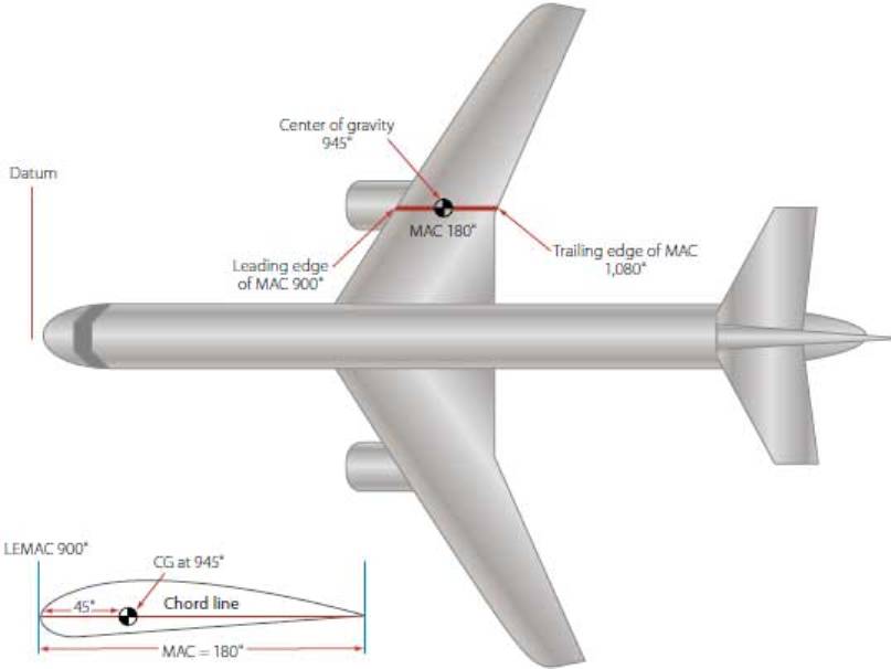
Center of gravity location on a large commercial transport
Figure above shows a large twin-engine commercial transport airplane. The datum is forward of the nose of the airplane, and all the arms shown in the figure are being measured from that point. The center of gravity for the airplane is shown as an arm measured in inches. In the lower left corner of the figure, a cross section of the wing is shown, with the same center of gravity information being presented.
Measure the root and tip chord. Then draw the following lines on the plans:
-
At the root of the wing, draw a line parallel to the centerline of the fuselage extending forward from the leading edge and rearward from the trailing edge. Both lines should be the length of the tip chord.
-
Do the same thing at the tip but drawing the lines the length of the root chord.
-
Connect the ends of the lines so that they create an "X" over the wing panel. Where the two lines intersect is the spanwise location of the Mean Aerodynamic Chord.
-
If the plan indicates that the CG should be located at some percentage of the MAC, then measure the MAC and put the CG the given percentage back from the leading edge along the MAC. For example, if the MAC is 10" and the plan indicates the CG should be 25% back from the leading edge, then the CG is 2-1/2" back from the leading edge at the MAC.
This drawing should help you visualize what you need to do:
Minimum Equipment List:
One of the important things the pilots will check is the “Minimum Equipment List “. Aircraft have a huge number of parts and like any machine, some of these parts may malfunction. Before a flight begins, the engineering team will check the aircraft out. They will inform the pilots about any defects they have discovered. Some defects are critical for safe flight and the aircraft will not be allowed to fly till these are fixed. However, more minor faults can be left to be fixed later if time is short or spare parts not readily available. The aircraft has a document called the “Minimum Equipment List “ which mentions the items that are absolutely necessary for the safe operation of the flight. If the defective item is in this list, then the aircraft is not allowed to fly till the item is repaired. If the defective part is not critical, then the flight can go ahead and the part repaired later.
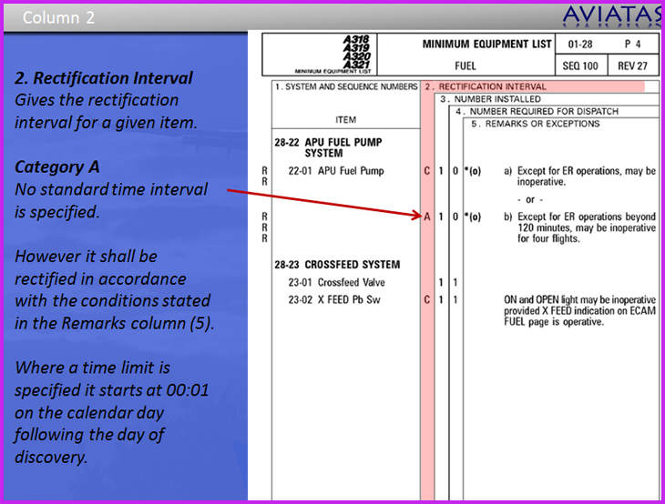
Here is an example of the Airbus A 320 aircraft MEL requirements of stuck out one detail that enables the Auxiliary Power Unit (APU) fuel system, 1 pump (APU fuel pump) inoperability, however, class "A" has a time limit, which means that if the planeIt does not perform ER (Extended Range) (long-range overseas flights, which ETOPS requirements apply) route. In addition, four routes allow completion of unserviceable fuel pump, lower at 120 minutes ETOPS flights.
Out flow valves:
The aircraft is a huge breathing system! However, unlike the breathing systems we use in anaesthesia, the patients actually sit inside the tubing!
Like any breathing system, you need fresh gas flow. This is taken from the engines. A little bit of the air sucked in by the engines is diverted into the cabin where the passengers sit.
Just like a circle breathing system used in anaesthesia, to save “fresh gas flow”, some of the air in the cabin is re circulated. This re circulation of air helps reduce fuel consumption since the engines have to work less hard.
Also like a circle system, the re circulation of air helps preserve heat and moisture. Carbon dioxide absorbers are not required because the fresh gas flow is quite high and this washes out carbon dioxide from the circuit. At the beginning of the flight, the pilots enter into the computer the number of passengers onboard. The computers use this information to determine how much fresh gas flow (air) to take from the engines and put into the cabin.
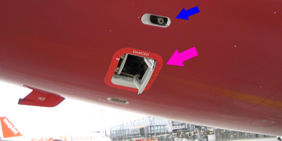
Air from the aircraft is exhausted via an out flow valve. In the picture above (pink arrow) the out flow valve is shown fully open.
The valve shown by the blue arrow is an over pressure valve. If, due to a fault, the pressure inside the aircraft builds up to a dangerous degree, this valve opens up to relieve the excess pressure, preventing the aircraft from rupturing like a balloon. This is similar to the over pressure valve found in anaesthesia machines.
RAM air turbine:
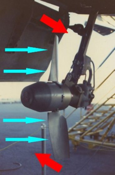
Just like in anaesthesia, aircraft have a lot of backup systems to cope with failure. One of the most interesting back up devices is what is called a “ram air turbine (RAT)”. If all electrical power fails in the aircraft, this device automatically gets deployed. It is basically a windmill. The airflow (shown with blue arrows) spins the turbine which in turn is connected to a small generator. This then powers essential equipment on the aircraft. The RAT is retractable to the aircraft fuselage (or wing), and it can be issued manually or using an aircraft batteries automatically.
Rotate:
Pilots share duties in the flight deck. There is a concept called "area of responsibility", everyone is responsible for using switches and displaying required information in their "area of responsibility". The area is mostly physical, the closest person is responsible for that part, but some parts are shared. Those shared parts have a different "owner" according to the role. For a given flight from a to b, a pilot has one of the two roles: he is either the pilot flying (PF) or pilot non flying (PNF).
During takeoff, while the PF takes care of the controls, PNF is responsible for the indications and "callouts" like "rotate". Yes, pf also aware of the speed but this concept makes each pilot aware and agree on every single event in the flight deck.
What many does not know is 'rotate' is just not a fancy word, but it involves a real physical rotation. When Rotation speed (Vr) is reached, the pilot pulls the control column which deflects the horizontal stabilizer, causing a rotation along the lateral axis of the airplane lifting up the nose wheel.
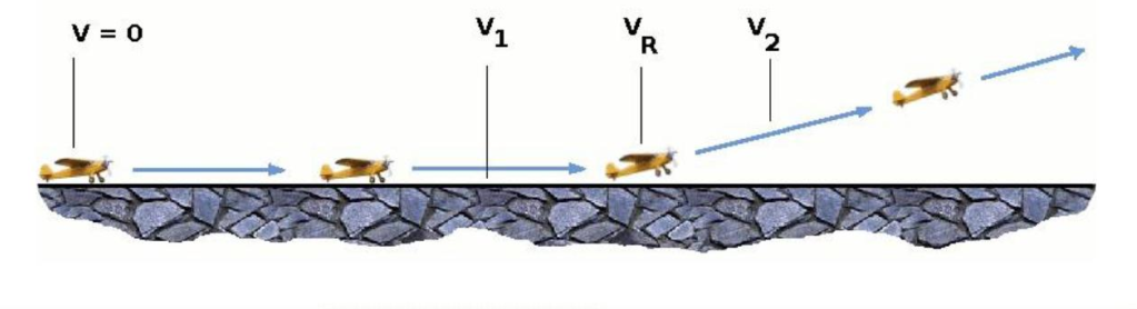
V1 = Famously known as the point of no return. V1 is the speed at which the pilot must decide to reject the take off. If speed exceeds V1, the take off must be continued as there will not be enough runway to stop. V1 should not be lower than Vmcg (minimum ground control speed). Vmcg is the speed at which the airplane rudder has enough air flowing over it. This ensures the airplane is controllable in the event of an engine failure.
Vr, should not be less than:
- V1
- It should be such that V2 can be obtained before the screen height (35 feet).
- 1.05 Vmc
V2 = This is called the take off safety speed. The speed should not be lower than V2min, V2min is the take off safety speed with critical engine inoperative. V2min should not be lower than 1.13 Vsr (stall reference speed) for 3 engined turboprops and all turbojets without provisions for obtaining a significant reduction in the one-engine-inoperative power-on stall speed. 1.08 Vsr for 4 engined turboprops and all turbojets with provisions for obtaining a significant reduction in the one-engine-inoperative power-on stall speed.

Here is a fine picture of a plane rotating
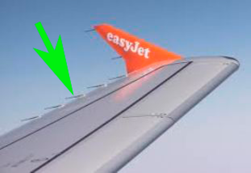
Static Discharge Wicks:
The purpose of static discharge wicks is to dissipate the static electricity that builds up on planes in flight. Most of us are familiar with static electricity in our daily lives. Common examples include the static cling in fabrics after being removed from a clothes dryer and the shock you may feel after rubbing your feet on thick carpeting or after stepping out of a car. Perhaps the most powerful example of static electricity is a bolt of lightning.
Static electricity is created when objects with different electrical properties come into contact, and negatively charged electrons from one substance are transferred to the other. This electron imbalance causes the object losing electrons to become positively charged while the other becomes negatively charged. The transfer of electrons is often aided by friction when two objects rub together, such as rubbing a balloon against your hair that causes hair to stand up. The same effect occurs on an aircraft due to the friction against the plane as it moves through the air. This friction strips electrons from the atmosphere and causes them to build up on the skin of the aircraft.
The creation of static charges is largely dependent on the ability of the two substances to conduct electricity. Metals are good conductors and allow electrons to flow freely through them. Other materials like rubber and air tend to be good insulators since they conduct electricity poorly. However, the ability of a substance to conduct electricity can also vary significantly with conditions. Air, for example, is typically a much better insulator at higher altitudes where aircraft fly because the atmospheric conditions here are much less humid than at low altitudes. As a result, a static charge that builds up on an aircraft at high altitude tends to become much larger because the air acts as an insulator preventing the excess electrons from returning back to the air.
This electrical charge can eventually become so great that the excess electrons begin to ionize local air particles and create a corona around parts of the plane. This corona causes electrons to discharge back into the surrounding air and dissipates the charge on the aircraft. Unfortunately, the coronal discharge most often forms on surfaces like communication and navigation antennas that transmit and receive radio waves. This ionized corona causes interference that reduces the effectiveness of communication gear or blocks reception entirely. NASA research has indicated that the interference typically occurs over a range of frequencies between 10 kHz and 350 MHz where most radios and other communication gear operate. An extreme example of ionizing interference occurs during re-entry when a spacecraft's high speed causes such intense friction against the atmosphere that the surrounding air is turned into ionized plasma and communications are lost for several minutes.
The static charges that build up on an aircraft during flight tend to accumulate near sharp edges like the trailing edges of wings and tail surfaces. The purpose of static wicks is to provide a conductive path for these excess electrons to flow or "leak" from the aircraft back into the atmosphere. This transfer of electrons reduces the charge on the plane's skin and structure.
The wicks are composed of hundreds of individual carbon fibers wrapped into a cylinder around three to eight inches (7.6 to 20.3 cm) long and about the diameter of a soda straw. Each fiber ends in a sharp point to create a strong gradient in the local electrical field. This gradient attracts the static charge and encourages the electrons to flow off the aircraft and back into the atmosphere. Instead of an ionized corona building up on vital communication antennas, the electrical charges find these wicks more attractive.
Static discharge wicks also provide other important safety benefits. In the event of a lightning strike, a plane is designed to conduct the excess electricity through its skin and structure to the wicks to be safely discharged back into the atmosphere. Though this massive electrical charge often burns or melts the wicks, these devices are simple and easy to replace. Wicks are also relatively fragile and easy to damage, so pilots and ground crew routinely inspect them in case replacement is needed. Because of their importance, regulatory agencies like the Federal Aviation Administration (FAA) require static wicks aboard all civil aircraft.